
Modelling Violin Modes
Introduction
In Figure S1 we first describe how the modes of the initially freely supported plates are transformed, when coupled together around their edges by the ribs, into those of the empty body shell. This relationship is of considerable interest to violin makers, who traditionally bend and twist the plates and listen to their ringing sounds when tapped, as they are being carved from solid wedges of wood. Experience then enables them to selectively thin the plates to achieve what they consider the optimal properties required to make a good sounding violin. In the mid 1960’s, Carleen Hutchins (1962, 1981) quantified such measurements using Chladni patterns (Chladni, 1787) to determine not only the resonant frequencies of the lightly supported plates excited by a loudspeaker, but also to monitor and control their mode shapes using Chladni nodal line patterns. However, the relationship between the free plate frequencies and mode shapes and those of the assembled violin was not understood.
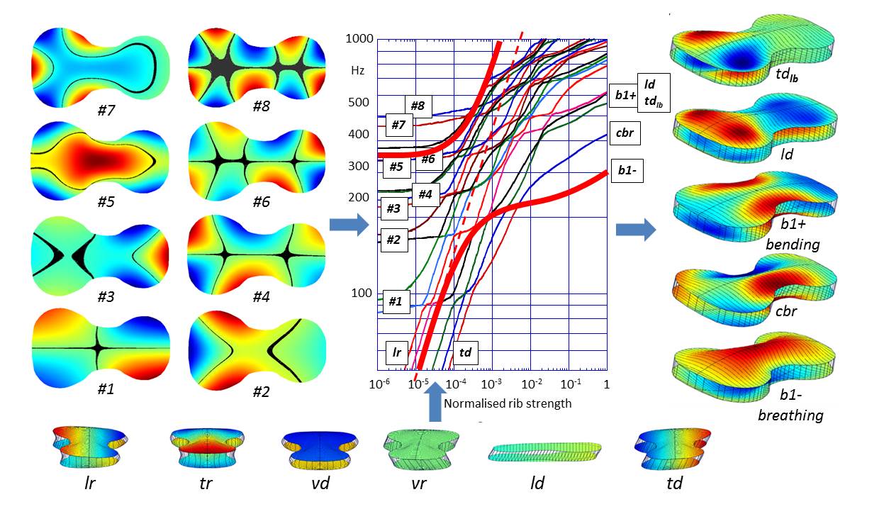
Figure S1. The transformation of the modes of the freely supported top and back plates into those of the assembled shell, as a function of increasing normalised rib strength varied over six-orders of magnitude.
The vibrational modes of the rib-coupled top and back plate modes have therefore been computed as the coupling strength of the ribs is increased over six-orders of magnitude from near zero (freely supported plates) to a typical value for 1 mm thick, 3 cm high, ribs. This is illustrated in Figure S1, with the first eight modes of the freely supported plates illustrated on the left hand side of the plot and the first few resulting shell modes at full rib coupling strength to the right – with the shell vibrations illustrated as a video sequence (video S1).
Visualisation of empty shell modes in vacuum before opening f-holes or adding bass bar. Ribs are transparent to view back plate vibrations as well as top.
Below the plot are another set of quasi-rigid, strongly interacting, plate modes, with frequencies increasing rapidly with increasing rib strength (initially with slope ½ as plotted on both logarithmic axis). These modes describe the initial six-degrees of freedom of the rigid plates moving and rotating freely in opposite directions, but now constrained by the bending, shearing and stretching of the ribs. The strong interaction of these modes with the initially freely supported plate modes result in the complicated plot of shell mode frequencies with increasing rib strength. At full coupling strength, the frequencies of the quasi-rigid plate modes are well above those of the coupled plate modes. But they still account for the stretching, bending and sheering of the ribs constraining the edge vibrations of the top and back plates in the modes of the assembled instrument.
The rib coupling strength was varied by scaling the Young’s modulus and the density of the ribs by the same scaling factor, to avoid complications from the multiplicity of low frequency rib modes, which would otherwise dominate the plot at low coupling strengths, if only the Young’s modulus is- varied.
Plate modes
The illustrated initially freely supported plate modes are those of the top plate without f-holes. The modes of the back plate are essentially the same, but with a re-ordering of modes #3 and #4 because of its slightly different arching profile. The modes are those of flexural or bending waves first described mathematically by Sophie Germain (1816). She showed that the flexural waves involved the spatial variation of the curvature or bending of the plates proportional to rather than the out-of-plane z displacement. The resulting wave equation is therefore 4th– order in the spatial co-ordinates rather than the more familiar 2nd– order equation wave equation for sound waves in air, liquids and solids. As a result, there are two types of flexural wave solutions for a thin plate – the familiar 2-dimensional half-wavelength sinusoidal standing wave solutions within the plate boundaries and exponentially damped standing waves around their edges. Similar exponentially damped thin plate solutions exist round the edges of the f-holes and ends of the sound post wedged between the top and back plates on instruments of the violin family.
Figure S1 shows that the initially freely supported plate modes all involve strong contributions from edge modes around the perimeter. These are required to satisfy the boundary conditions around the edges – no constraints on edge displacements, slopes or curvatures. Of the illustrated modes, only mode #5 has a standing wave within the plate. The mode frequencies increase with the number of standing waves around the perimeter.
Modes tend to be localised first in the larger area lower bouts then in the upper bouts at a higher frequency. This is also true for the modes of the assembled shell, where localised wave solutions in the lower and upper bouts appear first in the top plate and at a higher frequency in the thicker and heavier back plate. At higher frequencies, reliably computed up to at least 10 kHz, the modes of the assembled violin are determined by the ability at a given resonant frequency to fit standing waves of similar wavelengths into the different areas and elastic properties of the upper and lower bouts of the top and back plates. The localised waves are coupled by the ribs and their penetration into the island area between the f-holes and waist, where they can be excited by the forces of the bowed string supported by the bridge.
Rib coupling
Returning to the plot in Figure S1, we see that as soon as the free plates are coupled around their edges by the ribs, two independent normal modes are formed from the now rib-coupled top and back plates modes vibrating in either the same or opposite directions. Because the plate edges are constrained by the stretching of the ribs, the frequencies of the normal modes formed from component plate modes vibrating in opposite directions increase very rapidly – from the additional potential energy required both to stretch the ribs and to suppress the relative motion of the plate edges moving in opposite directions. In contrast, the frequency of the normal modes formed from the top and back plate modes vibrating in the same direction are initially only weakly increased by rib extensions – because their edges are already moving together in the same direction.
This is exactly what is expected from their coupling to the rapidly rising frequency quasi-rigid plate modes describing the initially rigid plates moving and rotating in opposite directions under the influence of the ribs. These modes will clearly interact strongly with those modes sharing a similar symmetry, but not with coupled plate modes vibrating in the same direction. This explains the very different rib strength dependence of the pairs of normal modes formed from plates moving in the same or opposite directions.
Shell modes
Without attempting to describe the complexities of the complicated mode diagram, we focus on how the rib coupling results in the formation of the acoustically important component b1- breathing and b1+ bending body shell modes, which themselves are coupled together to form the dominant B1- and B1+ acoustic modes of the violin body shell illustrated in Figure 4 of the main article.
The heavily emphasised curves in Figure S1 describe how the important breathing mode of the empty shell is formed from the interaction of the #5 plate modes vibrating in opposite directions with the quasi-rigid vd (vertical displacement) bouncing mode of the two plates initially vibrating as rigid bodies constrained by the stretching of the ribs around their edges. Both modes involve large changes in volume and are therefore strongly coupled.
On increasing the rib coupling strength, the frequency of the bouncing mode approaches and, in the absence of coupling, would cross that of the initial #5 mode. As with any pair of coupled oscillators, this leads to a veering away in opposite directions of the resulting mode frequencies from their otherwise uncoupled frequencies – as illustrated by the thicker curves. At the coupling strength at which their uncoupled modes would otherwise have crossed (coincidence), the resulting normal mode frequencies are split, with the bouncing and coupled pair of #5 plate modes vibrating with equal energies in the same and opposite phases. For coupling strengths above coincidence, the lower frequency mode is smoothly transformed into the body shell breathing mode, with now only a small amount of rib stretching at a typical coupling strength. The frequency of the resulting breathing mode is lower than the #5 free plate mode, but is still increasing quite rapidly at normal coupling strength, which will be increased by the corner and end blocks, when added.
The initial transformation from freely supported plates to shell modes with the vibrating edges of the plates tied together by the ribs is essentially completed at very small coupling strengths (around 10-3 full coupling). The plates are therefore effectively pinned to the ribs, but with edges of the arched free to expand and contract in the rib plane – as when an arched plate resting on a flat plane is pushed downwards. However, as the rib coupling strength increases, the plate edges are further constrained by the bending of the ribs. As the bending constraints increase, the plate edges become progressively clamped, first to the rib plane and then to the geometric rib outline at very much higher frequencies, well above those at typical coupling strengths.
In contrast, the important bending mode of the body shell is derived from the normal mode pairs of the now coupled #2 and #3 free plate modes vibrating in the same directions. Coupled plates with similar free plate mode frequencies (typically within a semi-tone or two) vibrating in the same directions involve only small changes in volume and are therefore radiate very little sound in the signature mode monopole frequency range. The coupled plate modes are also unaffected by the rising frequency quasi-rigid modes, with their frequencies crossing without any visible veering or splitting. The lowest frequency of the four normal modes formed from the rib-induced bending coupling of the in- and out-of phase vibrations of the #3 and #4 plate modes is then smoothly transformed into the anticlastic (bending in opposite senses along and across the length) b1+ bending mode of the assembled shell, which retains the large edge displacements around the plate edges, as illustrated in Figure S1 and video S1.
Despite the complexity of the mode plot, it is possible to describe how each of the vibrational modes of the assembled shell illustrated to the right of the plot is transformed from the initial plate modes and their interactions with the rising frequency quasi-rigid modes (Gough, 2013b).
The resulting lowest frequency body shell modes have remarkably simple shapes. The b1– breathing, and both the ld longitudinal and tdlb lower bout transverse and tdub upper bout transverse diploe mode (not illustrated) are exactly what one might have anticipated for identical plates vibrating in opposite directions, partially pinned or clamped around their edges. The cbr and b1+ bending modes retain their large edge displacements and are clearly directly related to those of freely-supported plate modes, though at significant highly frequencies.
Higher frequency, dipole, quadrupole, and multipole edge modes constrained within the upper and lower bout edges are confirmed by the computations and experimental modal measurements of Bissinger (Zygmuntowicz, 2009) and Stoppani (2015).
Because the acoustically important breathing mode involves very little edge motion, there has been renewed interest in developing ways to characterise individual plates during the carving process, using pinned rather than freely supported edges, but still free to move around the edges along their length and width [(Jansson and Niewczyk, 1989) and (Stoppani, private communication)].
Coupling to Helmholtz f-hole resonance
The above in vacuo computations neglected any coupling to the air within the cavity. This is most conveniently considered via the coupling between body shell modes to the Helmholtz f-hole mode, as illustrated in Figure S2. This also illustrates the veering and splitting of the B1- and B1+ modes formed from the coupling of the component breathing, bending and longitudinal dipole modes as their uncoupled frequencies would otherwise have crossed.
An uncoupled Helmholtz resonant frequency of 300 Hz was assumed. This is independent of pressure depending on the pressure-independent speed of sound in air, the f-hole shape and shell volume. However, the coupling to any volume-changing body shell mode increases with the density of the enclosed air – proportional to the ambient pressure. As indicated in Figure S2, a pressure of only one-tenth normal atmospheric pressure introduces already induces a strong splitting and veering of the initially close in frequency B1- and A0 normal modes describing the coupled, in- and out-of-phase vibrations of the component breathing and Helmholtz modes.
Increasing the pressure increases the coupling between the breathing and Helmholtz component modes depressing frequency of A0 still further below that of the uncoupled Helmholtz resonance. Coupling to the Helmholtz air resonance results in a corresponding increase in B1– frequency, which retains its largely breathing mode character. In the absence of an offset sound post, there is no coupling to the volume-conserving cbr mode, but considerable veering in frequency and splitting of mode frequencies as the B1- approaches and in the absence of coupling would cross the frequencies of the higher frequency bending and ld longitudinal dipole modes.
The coupling between the rising frequency B1- mode (breathing + Helmholtz) and the bending and longitudinal dipole modes of the empty shell results in three normal modes in the cross-over region, with combinations of all three coupled component modes in different proportions. The breathing component mode is now shared between all three modes. These are illustrated in the video sequence video 2, for the violin shell with f-holes and bridge. The motion of the disc in the videos illustrates the associated flow of air through the f-holes – a measure of the breathing component in each mode.
Empty shell modes with open f-holes at twice normal ambient pressure. The circular disc moving up and down represents air flowing in and out of the f- holes.
In Figure S2, the B1- and B1+ mode shapes at twice normal ambient pressure clearly illustrate the in- and out-of- phase vibrations of the coupled bending and breathing modes. Also illustrated is the reversal of the base-ball-like nodal lines across the top and back plates. This an important property of the observed B1- and B1+ modes, which is automatically described by the coupled vibrations of the bending and breathing modes of any shallow box with arched plates.
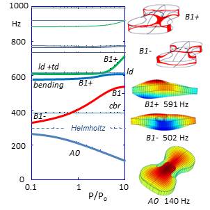
Figure S2. The influence of pressure on the coupling of the Helmholtz f-hole resonance to the component body shell modes. The illustrated mode shapes are those of the A0, B1- and B1+ modes at twice normal ambient pressure including the reversal of the baseball-like nodal lines of B1- and B1+.
This coupling arises from the longitudinal strains induced by flexural waves on any arched surface. Because the top and back plates are non-identical, the flexural strains induce different changes in the length and width of the top and back plates, which is very pronounced for the breathing mode. This results in a bending of the shell structure rather like the bending of a bimetallic strip when heated – from the differential thermal expansion of the top and back strips made of different metals.
As a result of such coupling, the B1– and B1+ resonant frequencies will always be split by at least an amount that depends on the difference of their arching-induced expansions of the top and back plates.
At low pressures, only the component breathing mode increases with increasing ambient pressure. It immediately follows that none of the higher frequency component modes involve a significant volume-change. Hence, none of them will contribute significantly to monopole radiation in the signature region below around 1 kHz, other than via their coupling to the breathing mode. This validates our earlier claim that almost all the sound radiated by the violin in the monopole signature mode frequency range is radiated directly by the component breathing mode and indirectly by its coupling to the Helmholtz f-hole resonance and otherwise non-radiating component modes (Gough, 2015b).
The monopole source strengths of the B1- and B1+ modes is determined by the coupled component breathing and Helmholtz modes in each, which is strongly dependent on the relative frequencies of the uncoupled bending and breathing modes. This accounts for the relative intensities of the B1- and B1+ modes in the acoustic spectrum, which varies from instrument to instrument.
The sound post and bass bar
Finally, we consider the sound post – in French (l’âne) and Italian (l’anima), the soul of the violin – expressing its major influence its sound.
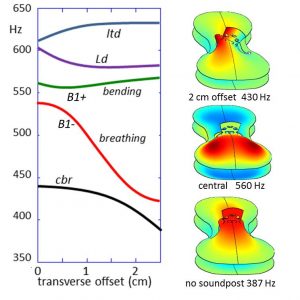
Figure S3. The influence of transverse offset of sound post position on the empty shell mode frequencies. B1- mode shapes are illustrated without a sound post, for a centrally placed sound post and offset by 2 cm.
The soundpost has a particularly strong influence on the breathing component of the B1- mode, as illustrated in Figure S3. At low frequencies, a well-fitted soundpost acts as a rigid constraint tying the displacements and slopes of the top and back plates together across its ends. This introduces a rapid depression of the mode shape towards zero across its ends – described by the addition of the radial equivalent of the previously described exponentially decaying edge modes.
The soundpost therefore act as a barrier or gate inhibiting flexural waves from moving from the lower into the upper bouts via the island area – and vice versa. When a centrally placed sound post is inserted between the top and back plates frequency of the acoustically radiating breathing mode increases from 387 to around 560 Hz – a musical interval of around a perfect fifth, where it interacts strongly with both the bending and longitudinal dipole components, resulting in the splitting of veering of the modes illustrated in the plot. Video 3 illustrates the influence of a 2 cm sound post offset on the shell mode shapes. This demonstrates the relatively weak influence of the sound post on the lowest frequency mode shapes other than in the island area close to the sound post.
Shell modes without bass bar but with a 20 mm offset sound post to illustrate asymmetry of resulting shell modes and coupling of breathing mode to previously non-radiating modes.
Offsetting the sound post sideways opens up a wider gap on the bass side of the island area. This enables the breathing mode vibrations in the lower bout to penetrate further in to the island area and beyond, with a resulting reduction in frequency from 560 to 430 Hz. Such a mode shape was observed in early holographic measurements by Jansson et al (1970) and confirmed in many later experimental modal analysis measurements.
The strongly localised perturbation of the breathing mode shape in the island area by the offset sound post also enables it to be strongly excited by bowing forces parallel to the plates. The efficiency with which sound can be excited is therefore strongly dependent on sound post position, which is a very important factor in setting up an instrument for optimum performance.
The bass bar which runs beneath the bass-side foot of the top plate into the lower and upper bouts also perturbs mode shapes by inhibiting bending (curvature of the waveform) along its length. This strengthens the penetration of flexural waves though the island area between the lower and upper bouts bout into the upper bouts. It also acts as an asymmetrical barrier tending to localise standing waves to one side or other of its length.
The neck, fingerboard and all other attachments
The neck and fingerboard are rigidly connected to the top end of the body shell. Adding a rigid neck-fingerboard assembly introduces six new vibrational modes derived from its six displacement and rotational degrees of freedom with frequencies constrained by the flexibility of the shell structure supporting the neck. This results in six new normal modes describing the in- and out-of-phase coupled vibrations of the neck and body shell. Acoustically the most important mode is a cantilever-like, rigid neck-fingerboard vibrational mode along the length. This introduces a new body-shell mode, which is often close to the A0 resonance and also results in a slight depression of the bending mode frequency but with only a minimal influence on the other body shell modes (Gough, 2015b).
Likewise, the non-radiating vibrational modes of the fingerboard, neck, tailpiece, higher frequency air modes such as the a1 longitudinal dipole, the strings, tailpiece, etc. will all couple to the body shell modes to some extent. Their in- and out-of- phase coupled vibrations result in additional normal modes appearing as additional substructure and sometimes splitting of the dominant signature modes evident in Figure 4 of the parent article. In general their influence will be limited to a very small frequency range around their individual resonances, so will only affect the sound of an instrument on the partials of bowed notes within a semitone or so of their resonances. The computer model allows the influence of all such components to be smoothly increased from zero, to demonstrate how each one would affect the body shell modes and the radiated sound in the monopole signature regime.
Higher frequency modes
Although this article has focussed on the vibrational modes in the low frequency signature mode regime, the computations with typically 50-10,000 degrees of freedom provide reliable mode shapes and frequencies up to at least 10 kHz. Preliminary studies have already provided useful insights into the density of acoustic states over the whole frequency range and the function of the bridge and island area in controlling the high frequency response, but have yet to be published.
Summary
Recent collaborations between acousticians, makers, players, dealers and museum curators have resulted in a dramatic increase in our knowledge the acoustical properties of a large number of outstanding violins by Stradivari, Guarneri and their contemporaries. This has benefited greatly from the development of pc-based digital data acquisition and analysis software, which can be used whenever and wherever there are classic Italian or modern violins to be measured. Our understanding of the body shell vibrations of the violin and related instruments has also advanced significantly – especially from the experimental modal analysis investigations of Bissinger (2008 a,b) and Stoppani (2013). In parallel, our COMSOL finite element shell structure computations have led to a model for the body shell modes of the violin and related instruments, which for the first time demonstrates the relationship between the freely supported plate modes and the acoustically important modes of the fully assembled instrument and their dependence on all its component parts.
Additional reading
An earlier introduction to the science of the violin written for Physics Today (Gough, 2001) http://physicsworld.com/cws/article/print/2000/apr/01/science-and-the-stradivarius provides an introduction to the acoustics of the violin for a more general audience including violin makers and students undertaking projects on bowed string instruments. One of Carleen Hutchin’s major legacies was her compilation, editing and introductions to almost all the important papers on violin acoustics from the time of Savart until 1996, published in two 2-volume sets (Hutchins, 1975 and 1997). In addition, many interesting articles on the violin by both makers and acousticians can be found in the Catgut Society of America’s journals edited by Hutchins, which are now freely downloadable (Catgut Society of America, 1964-2004) https://ccrma.stanford.edu/marl/CASL/CASLhome.html. Cremer’s The Physics of the Violin (Cremer, 1984) remains the most important book on violin acoustics, but is now rather dated because of more recent advances. The Springer Handbook of Acoustics edited by Tom Rossing contains a lengthy chapter on Musical Acoustics, with a section on stringed instruments (Gough, 2007). Eric Jansson from the Musical Acoustics Group at KTH in Stockholm has published a very useful introduction to the Acoustics for Violin and Guitar Makers http:/www.speech.kth.se./music/acviguit4/part7.pdf, and many useful articles can be found on the German violin maker Martin Schleske’s web-site at http://www.schleske.de/en/our-research.html. JimWoodhouse (2013) at Cambridge University has also recently published an authoritative, up-to-date, comprehensive review of violin acoustics.
References
Bissinger, G. (2008a). Structural acoustics of good and bad violins, The Journal of the Acoustical Society of America 124, 1764-1773.
Bissinger, G. (2008b). Structural acoustics model of the violin radiativity profile, The Journal of the Acoustical Society of America, 124, 4013-23.
Catgut Society of America, 2016. Catgut Acoustical journals,
Chladni, F. (1787). Entdeckungen über die Theorie des Klanges (Discoveries in the Theory of Sound), Leipzig.
Cremer, L. (1984). The Physics of the Violin (MIT Press, Cambridge)
Germain, S. (1816). Recherches sur la théorie des surfaces élastiques, the 3000 francs prize-winning essay awarded by the French Academy of Sciences (Stӧckmann, 2007).
Gough, C. (2000). Science and the Stradivarius, Physics World 13, 27-33.
Gough, C. (2015a). Violin plate modes, Journal of the Violin Society of America 20,161-174.
Gough, C. (2015b). A violin shell model: vibrational modes and acoustics, The Journal of the Acoustical Society of America 137, 1210-1225.
Gough, C. (2007). Musical Acoustics, in Springer Handbook of Acoustics (Springer).
Helmholtz, H., (1863). On the sensations of tone (Dover publications) first published in 1863 with a 4th edition in 1885.
Hutchins, C.M. (1962). The Physics of Violins, Scientific American (November), 78-93.
Hutchins, C.M. (1981). The Acoustics of violin plates, Scientific American (October), 126-135.
Schelleng, J.C. (1971). The bowed string and the player, The Journal of the Acoustical Society of America 53, 26-34.
Schleske, M. (1996). On making Tonal Copies of a Violin, Journal of the Catgut Acoustical Society, series 2, 3(2), 18-28.
Stoppani, G. (2013). Acoustic measurements in the workshop”, in proceedings Stockholm Musical Acoustics Conference 2013, 16-23.
Woodhouse, J. (2014). The acoustics of the violin: a review, Reports on Progress in Physics 77, 115901. http://iopscience.iop.org/article/10.1088/0034-4885/77/11/115901/pdf.