
Page 33 - Fall 2006
P. 33
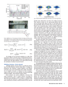
  Fig. 19. Mobilities of a 7.62 mm diameter Schedule 40 steel pipe with elbow meas- ured at different locations along the length compared to infinite beam and infinite shell mobilities. n=2 circumferential motion cuts on at 2 kHz, and the pipe transi- tions from beam-like to shell-like vibration.
 ,
and Y = .
,
(27a)
(27b)
(27c)
  An example of the measured mobilities in a pipe (this one with an elbow) is shown in Fig. 19 (adapted from Doty25). Mobilities measured at several locations are compared to the infinite beam and shell mobilities, once again demonstrating the usefulness of infinite structure theory.
Modeling vibrations—Finite elements
Although infinite structure theory is useful for estimat- ing structural vibration and the mean effects of changes to parameters like thickness, Young’s Modulus, and density, sometimes more exact knowledge of the modes and mobili- ties of complex structures is required. In these situations, analysts often turn to the most popular structural modeling method available—finite element analysis (FEA).
Finite elements are used to subdivide a structure into small increments, each of which behaves according to assumed local functions, usually linearly or quadratically. The textbook by Zienkiewicz26 is generally recognized as the most authoritative summary of finite element theory, and can
  Fig. 20. Measured and simulated (FE) mode shapes of a free square glass plate.
provide more detail than I do here. For simple structures, finite element models can be constructed quickly, like the ones of the glass plate shown in Fig. 20. The modes for the glass plate finite element model, constructed using plate ele- ments, were computed using a widely available commercial code, and compare well to those measured with accelerome- ters and force hammers. The mode shapes match almost exactly, which is not surprising for a simple plate, but the res- onance frequencies differ slightly. Discrepancies between the resonance frequencies of FE and actual mode shapes are common, and are usually caused by mismatches between the modeled and actual geometries and material properties. Often, the properties of FE models are updated to better reflect reality when measured data are available.
For plate and beam finite elements, nearly all commer- cial software includes rotary inertia and shear resistance by default (these are important for thick beams and plates, remember?). Also, a limitless variety of cross-sections and inhomogeneities along the beam/plate lengths can be mod- eled simply with finite elements. For thick-walled structures, solid continuum elements are used, and may also be used to
12 model thin sheets of viscoelastic damping material .
The main usefulness of FEA is its ability to simulate the response of complicated structures. Examples of a propeller, modeled with solid continuum elements, and a rib-stiffened metal equipment enclosure, modeled with plate and beam elements, are shown in Fig. 21. These sorts of models simply cannot be constructed readily with analytic or infinite struc- ture methods. Mode shapes are shown for both examples, and mobilities for drives at any location or orientation may be computed directly, or as a summation of the mode shapes, just as we learned for flat plates earlier.
In the propeller mode example, the blades vibrate torsion- ally, and behave like plates cantilevered from the hub. The rel- ative phasing between the individual blade vibrations is based on the circumferential harmonic (n) of the mode shape, where the hub behaves like the cylindrical shells we considered earli- er—with a cos(nθ) and sin(nθ) dependence on θ.
The motion in the modes of the equipment cabinet model is mostly localized to the panels between the frame. In the example, three of the panels on the right side of the cabinet vibrate like fundamental plate modes with clamped edge con- ditions, but with different relative phasing: the top panel vibrates out of phase with the bottom panel. Sometimes, the vibrations of panels in framed structures, like airplane fuselages and ship hulls, may be approximated with simple plate theory.
Structural Acoustics Tutorial 31
