
Page 30 - Summer 2008
P. 30
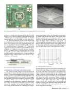
  Fig. 3. Dual-axis 2g accelerometer at two magnifications showing accompanying electronics (A) and sensors (B.)
 of one g or hundreds of g’s with bandwidth as high as 20 kHz. Figure 3 shows a dual axis MEMS accelerometer mounted on a substrate with its accompanying electronics (A). Further magnification (B) reveals the MEMS structures themselves.
The MEMS accelerometer structure can be connected to the conditioning electronics either on the same chip as the sensor or on a separate chip. In the case of a single chip solu- tion the capacitance of the sense element can be as low as 1 to 2 femtofarads per g (1 femtofarad = 10-15 farads which equates to measurement resolutions in the attofarad range (1 attofarad = 10-18 farads). In a two chip structure, the capaci- tance of the MEMS element is typically higher to overcome the parasitic capacitance effects of the bond wires between the MEMS and the conditioning ASIC (Application Specific
2
Integrated Circuit). Figure 4 shows a cross-section of a typi-
cal two-chip accelerometer.
  Fig. 4. Cross-section of a typical two-chip accelerometer.
 cation due primarily to the narrow bandwidth of commercial- ly available small acceleration sensors. Some recent break- throughs in accelerometer technology have enabled the pro- duction of very small accelerometers with very wide band- width. The Analog Devices ADXL001 is a high g (±70 g to ±500 g) single axis accelerometer that has a bandwidth of 22 kHz that comes in a 5 mm x 5 mm x 2 mm package (See Fig. 5). This is ideal for vibration monitoring in industrial applica- tions. It is particularly suited to high g applications such as
Fig. 5. ADXL001 frequency response curve.
condition monitoring of motor life and general machine con- dition by detecting changes in bearing acoustic characteris- tics. In the early stages of bearing wear a clear vibration sig- nature develops in the audio band that can be detected with a high g vibration sensor attached to the system housing. This particular sensor is not suitable as an acoustical vibra- tion sensor for musical instruments because it measures acceleration in the order of tens of g’s and is therefore not sensitive enough. Also, it only senses along one axis of motion while an ideal acoustic sensor will have a desired response in all three axes. However, it does demonstrate that full audio bandwidth acceleration transducers can be pro- duced using MEMS technology.
  Accelerometers as vibration measurement sensors
The concept of using vibration sensing transducers for
measurement of acoustic vibration in musical instruments is
3
not new. Piezo and electromagnetic transducers are the basis
for many acoustic pickup applications today and a discussion on the performance of these sensors would fill far more pages than this article would allow. It might be attractive to be able to add tiny MEMS accelerometers to the list of available transducers for such applications—transducers so small and low in mass that they have no mechanical or mass loading effect on the instrument. To date there has been limited suc- cess in using MEMS accelerometer technology for this appli-
Managing Acoustic Feedback 29
