
Page 12 - Jul2009
P. 12
installed on computers serving four independent work sta- tions. Although each workstation is nominally assigned to a specific research space, complex switching systems provide the ability to reassign any workstation to any research space. This switching system can be used to reassign network con- nections, serial ports, digital audio signal routing, and partic- ipant response systems to any desired configuration. This flexibility allows for the reconfiguring of systems to accom- modate any experimental configuration, or to continue oper- ating in the event of a workstation failure.
Real time audio and video monitoring is accomplished through pairs of wall-mounted cameras and microphones in each of the four indoor research spaces. The outputs of the cameras and microphones are routed to an audio/video switch in the Control Room. Audio signals can be routed to the 5.1 surround sound system mounted at the ceiling of the Control Room or to the headphones connected to each work- station. Video signals are supplied from fully adjustable cam- eras located in each indoor research space. Selected video sig- nals can be routed to dedicated monitors located at the indi- vidual work stations or to one of two 43 inch liquid crystal displays (LCD) mounted on the Control Room wall. The audio and video capabilities of the Control Room have been designed to provide audio-video demonstrations and instructions for new users, to monitor participants during experiments, and to enable individuals to observe the exper- iments without interrupting data collection. Two-way voice communications via a stand-alone professional-grade inter- com system is also available between the Control Room and each of the indoor research spaces.
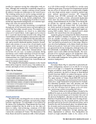
The wiring for all loudspeakers terminates in the Control Room and the respective research spaces. The number of con- nections and lengths of wires are mind boggling (see Table 1).
Table 1: By the Numbers
er as 180 of them needed to be installed in a circular array within the given space. The output level requirements pushed the state-of-the-art beyond what was commercially available at the time. High intensity output is needed to simulate high noise military operational scenarios. SPL Integrated Solutions (now AVI-SPL) partnered with Meyer Sound Laboratory to develop a custom, self-powered loudspeaker which meets the acoustic power requirements while main- taining a frontal dimension of 4.04 inches. These loudspeak- ers provide the required auditory stimuli in our Sphere Room, Dome Room, and Distance Hall. The loudspeakers are closely matched in frequency response and output, and each contains an internal amplifier and a digital signal pro- cessing (DSP) module. There is a dedicated power supply located in the Control Room for each loudspeaker.
Automatic gating was incorporated by Meyer Sound into each DSP module to eliminate the typical “hiss” associated with the amplifier operating at maximum gain. Typically when loudspeakers are powered on individually, loudspeaker “hiss” can barely be perceived even at close range. However, since all of the loudspeakers in the Sphere Room and Dome Room are focused on a “sweet spot” in the center of the room, any generated hiss by one loudspeaker, although barely audi- ble individually is multiplied by the large number of loud- speakers and is easily audible and objectionable. The incor- poration of the automatic gating in the loudspeakers elimi- nated any perceptible “hiss.” (Meyer Sound offers a version of this custom-made loudspeaker to the public as the MM-4XP miniature loudspeaker.)
Sphere Room
The Sphere Room (Fig. 3), named for its spherical loud- speaker configuration, measures 5.3 m wide by 5.4 m long and is 4.9 m high. It is designed for investigations in the integrity of auditory virtual spaces, the realism of complex auditory simulations, the effects of changes in Head-Related Transfer Functions (HRTF) on auditory perception, and the effects of helmets and other headgear on spatial orientation. The room contains 57 Meyer Sound MM-4XP test loud- speakers. The loudspeakers are positioned at five levels of ele- vation plus a single loudspeaker mounted directly overhead. The azimuthal separation varies with elevation such that there are equally spaced separations of 20° at the 0° elevation, 30° at the ±30° elevations and 45° degrees at the ±60° eleva- tion, constituting a sphere surrounding the listener.
The listener station in the Sphere Room is located in the middle of the room on an elevated and adjustable platform so that the ears of the participant can be located at the center of the sphere of loudspeakers. Adjustments made with the com- bination of the platform and the chair cover the range of seat- ed heights between the 5th percentile female and the 95th percentile male so that the ears of virtually any listener can be located in line with the horizontal plane. An unlimited num- ber of sounds may be presented simultaneously to any com- bination of the loudspeakers. Moving sounds can be simulat- ed among multiple loudspeakers through panning algo- rithms implemented in software. Four loudspeakers are located on height-adjustable stands in the corners of the
Stimuli production
The EAR facility was designed to use as many common components as possible to minimize cost and reduce unique hardware requirements. This philosophy is best reflected in the choice of test loudspeakers. Requirements for these loud- speakers included that they be small in size (less than 4.25 inches in width), while producing a minimum of 85 dBA when excited with pink noise, at a distance of approximately 3 meters for a minimum of 2 hours. The dimensions of the Dome Room dictated the maximum width of the loudspeak-
The Environment for Auditory Research 11
