
Page 41 - Jul2009
P. 41
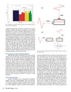
  Fig. 1. A graphic representation of channels and bands within a digital hearing aid. (Courtesy of Steve Armstrong)
 number of channels for each feature activated, such as noise reduction, adaptive directional microphones, and feedback management. A handle is a graphic representation of a con- trol on the computer screen. It is provided in the manufac- turer’s software to alter a parameter of the hearing aid, e.g., by sliding the control handle up or down. This GUI is function- al in a Windows environment. The use of handles is common among different manufacturers to permit the clinician to change the magnitudes and/or ranges of more than one band or channel at a time in a consistent manner. The interface allows the clinician to choose to make either more global or finer, more detailed, adjustments. The hearing aid depicted in Fig. 1, for example, has 16 bands (for gain shaping across frequency) and four channels for specific non-linear signal processing. The manufacturer may also choose to use four handles so that the clinician can adjust the response for the contiguous bands in one channel at a time.
Re-introduction of directional microphones
Although directional microphones have been used for many years in the electronic news gathering and recording industries, they first became popular in hearing aids in the mid-1970s. For a number of reasons, including the intro- duction of custom in-the-ear styles of hearing aids, their popularity waned until the late 1990s. The rationale for using directional microphone systems in hearing aid design is based on different spatial properties of speech and noise. Typically, speech comes from a listener’s front while com- peting noises come from the front and other directions other than the front. Directional technology has the poten- tial to improve speech intelligibility in noise because it can maintain sensitivity to sounds originating in the front of the listener, while reducing sensitivity to sounds at other azimuths.
Order of directionality
Another descriptor used in directional microphone design is the order of directionality. There are two com- monly used schemes in hearing aids today as shown in Fig. 2: a single microphone element (capsule) with two ports and two microphone elements (capsules–both omnidirec-
tional microphones) that are connected electrically. In each case, the designs are first-order directional systems; that is, two ports are used for sound entry to the diaphragm and the sounds from different directions are either reinforced or reduced based upon the slight differences in arrival time at each of the two sound entries (ports). A second-order direc- tional system can be achieved by adding one more omnidi- rectional microphone, in effect one more port, at a careful- ly defined spacing from the first port, sometimes mathe- matically calculating the necessary time delay. In effect, any higher order directional system can be labeled by the “num- ber of ports minus 1” rule. An omnidirectional microphone is technically a zeroth-order microphone. A first-order directional microphone system with two microphone ports typically has a free field directivity index of 6 dB or less. A second-order directional microphone system with three microphone ports typically has a free field directivity index of 6 to 9.5 dB. The recently proposed revision of Annex B of ANSI S3.35 (Method of Measurement of Performance Characteristics of Hearing Aids Under Simulated Real Ear Working Conditions) contains definitions for first- and sec- ond-order directional systems. The technical definition of
 40 Acoustics Today, July 2009
Fig. 2. (a) Shows a single-element directional microphone scheme. (b) Shows a two-element scheme.
