
Page 25 - Winter 2009
P. 25
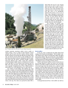
  Fig. 2. Drilling a steam well at the Geysers (Courtesy Calpine Corporation).
cyclonic separator sometimes called a blooie muffler, as shown in Fig. 2. This is a large, ten-foot diameter, vertical cylinder with the inlet off axis to induce cyclonic motion. Rocks are flung to the outside and collected in pockets where they can later be removed. Water is often introduced to cool the steam and reduce its volume, which lowers the flow noise. The steam exits the silencer vertically through a smaller, three-foot diameter pipe. Under strong flow conditions (170,000 lbs/hour) blooie silencers still generate loud noise levels (108 dBA at 50 feet without water injection and 103 dBA with water injection) and require large quantities of water, typically 150 gallons/minute. Thus a blooie muffler is more effective as a rock separator than as a noise silencer.
The realities of well drilling and handling the steam introduce a number of interesting engineering problems for which clever solutions have been developed by the drilling crew. A good example of the in-field ingenuity was the solu- tion to the valve replacement problem. Like oil wells, geot- hermal steam wells are drilled using long sections of pipe screwed together into a drill string. The drilled hole is cased with a steel pipe about twelve inches in diameter surrounded with concrete that has been fitted with one or more large gate valves at the top. The valves are operated by hand with a
Rock mufflers
24 Acoustics Today, October 2009
wheel about the size of a car’s steering wheel, and are used to cap the well or divert the flow when steam is encoun- tered. Due to the rocks and debris in the steam flow there is wear on the valves and they have to be periodically replaced. The practice is to use two or more valves, mounted on top of one another. After the drilling is finished the top valve can close off the well when necessary, while the bottom valve is used only when the top valve needs to be replaced. However, periodically, the bottom valve must also be changed.
The technique for bottom valve removal was to have a worker approach the valve, while the well was venting, and remove two bolts in the valve flange, one on either side of the pipe. He would then thread a large diameter steel cable up through the bolt holes and secure a cable clamp near the end of the cable. Tension was then taken up on the two cables using a D8 Caterpillar tractor. The volun- teer would then gingerly remove the remaining flange bolts and retire to a safe distance while tension was being main- tained on the valve via the tractor. The tractor would then drive toward the well to release the tension on the cables and allow the valve to dance around until it fell to the ground. To install the new valve the process was repeated in reverse, using a bucket loader to hold the new valve.
In free jets, noise is produced by the high velocity fluid mixing with the quiescent atmosphere. This is similar to air- craft exhaust noise, where the sound power follows the eighth power of the velocity. The cause of the noise is the turbulence created by the mixing, which occurs five to eight pipe diame- ters downstream of the pipe opening. Thus the key element in controlling the noise is to reduce the flow velocity.
Clearly, conventional mufflers would not work because the exit pipe diameter is almost the same as the inlet pipe diameter, so the flow would not slow down. The exit area had to be much larger than the entrance area. A silencer would also have to tolerate high velocity rocks and debris. I suggest- ed blowing the steam into the bottom of a large bed of rocks in a pit dug into the ground or placed in a large steel or con- crete enclosure. The open top of the pit would be the exit area, which could be made quite large. The pipe below the rocks extends across the enclosure to allow debris to impact against a steel plate at its end, which could be removed for cleaning. A perforated pipe could be used to distribute the steam evenly over the bottom of the pit. This was the first rock muffler.
I subsequently learned that a trial muffler was built on
