
Page 13 - Winter 2010
P. 13
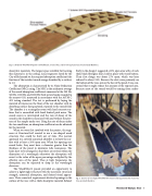
  Fig. 4. Rendered WoodWave© panel with bulkheads, stressed skin, and bowstring (Courtesy StructureCraft Builders).
absorptive materials. The largest space available for locating this material is in the ceiling. Local engineers hired by the City of Richmond set the required absorption coefficient (the fraction of the incident sound energy absorbed by a surface) to 1.0.
The absorption is characterized by its Noise Reduction Coefficient (NRC) rating. The NRC is the arithmetic average of the sound absorption coefficients measured at the 250 Hz, 500 Hz, 1000 Hz, and 2000 Hz third octave bands rounded to the nearest 0.05, measured in accordance with the ASTM C 423 testing standard. The test is performed by laying the material of interest on the floor of the test chamber with its absorbing surface facing upward, exposed to the sound field. The chamber is a rectangular room with hard concrete sur- faces that is ensonified with band limited pink noise. The sound source is interrupted and the rate of decay of the sound in the chamber is measured with and without the pres- ence of the sample under test. Using the rate of decay under the two conditions, an absorption coefficient can be obtained for the material.
When we were first involved with the project, the engi- neers at StructureCraft wanted to use a vee-shaped wood structure that could be built out of 2x4s. The normal approach to a covered acoustical absorber is to leave the sur- face with at least a 20% open area. When the openings are round holes, they must have a diameter greater than the thickness of the panel to minimize tube resonances. The holes have to be arranged so that there are several within the dimension of a wavelength otherwise the absorption will revert to the value of the open percentage multiplied by the effective area of the panel. Thus at high frequencies the absorption can be expected to drop as the wavelength decreases.
The WoodWave© panels provided an opportunity to achieve a lightweight structure with the necessary structural strength, acoustical absorption, and desired visual appear- ance. Their acoustical requirements dictated openings in the surface of the vees with a thick absorptive material behind.
Early in the design I suggested a 20% open area with a 2 inch thick black fiberglass liner, held in place with wood battens. Their first design was about 27% open, which was later reduced to about 24%. Because the slots were primarily on the bottom of the vees, not on the face of the panel, I was con- cerned that it might reduce the amount of the exposed area. Because most of the sound would be coming from under-
Fig. 5. Interior of vee-shaped WoodWave© structure during construction (Courtesy StructureCraft Builders).
 Richmond Olympic Oval 9
