
Page 18 - 2013 Spring
P. 18
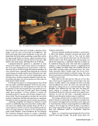
                                  Fig. 1. Interscope Records control room, showing flush-mounted loudspeakers, sloping ceiling, and side soffits.
hears both speakers (interaural crosstalk), a phantom center image is not the same as that heard on headphones. The direct path length from either loudspeaker to one ear is dif- ferent from that to the other, producing a comb filter with its first dip around 2 kHz. In contrast, a good ensemble of sym- metrical lateral reflections spreads out the sweet spot, adds depth to the stereo image, and helps fill in the 2 kHz dip.
Loudspeaker/listener geometry is controlled to some extent by the need for visual contact with the recording stu- dio. If the main loudspeakers are located above a wide win- dow then they are a little too high for optimum mixdown. In some control rooms, especially those designed for surround sound mixing, the studio window may be located to one side, allowing the front wall to be used for loudspeakers and a viewing screen. Another common alternative omits the cen- ter speaker and places two stereo speakers on either side of a fairly narrow studio window.
For the past ten years or so, mixing engineers have relied more on small, nearfield loudspeakers than the main moni- tors. The big speakers are still important, but they are used for periodic checks and for playback to the producer’s area. Therefore, the room must provide good stereo listening under three conditions: (1) main speakers to console, (2) nearfield speakers to console, and (3) main speakers to pro- ducer’s desk. Good correspondence between the two sets of speakers is important, and the main monitors are sometimes equalized to match a particular pair of console-top speakers.
Achieving acceptable low frequency response is much easier in a comfortably large mix room than a small produc- tion room, but audible peaks and dips below 100 Hz or so can be expected, and this is true for the nearfield speakers as well as the large monitors.6 Because of the requirement for good sound isolation, room boundaries do not dissipate very much low frequency energy. As a result, a substantial amount of interior volume must be used for broadband low
frequency absorption.
The most common broadband absorber is a cavity loose-
ly filled with fibrous absorptive material and faced with porous fabric. It is called a “trap” or “bass trap” by studio designers. The cavity must be more than two feet deep to be effective down to the 50 Hz region. Since the main goal is to absorb low frequencies, a substantial reduction in depth can be realized by facing the cavity with wood slats or pegboard, making it a low-Q Helmholtz resonator. A pegboard-faced wainscot, perhaps two inches deep, was a familiar feature of many older recording studios and control rooms. The writer favors somewhat deeper “bunker traps” that can be conve- niently located under windows or behind seating. The same basic construction can be built from floor to ceiling to create an effective corner trap.
Deep soffits on the side and rear walls can serve as bass traps. These may be augmented by vertical traps in the rear corners. In older rooms it was common to create a two-foot deep broadband trap across the entire rear wall, effectively placing the seating area in an acoustical black hole. Some designers later replaced the rear trap with very deep dif- fusers, hoping to scramble low frequencies rather than absorbing them, but the subjective results were equally unsat- isfactory. As with the side walls, a reasonable mixture of reflective and absorptive surfaces seems to work best.
The mixing console itself is an important but often over- looked element in optimizing low frequency reproduction. The console is the biggest piece of furniture in the room, and its exact location can have a surprising effect on audible bass response. Even though the console position is specified as part of the original room design, a six-inch shift forward or back will sometimes result in worthwhile subjective improvement.
Figure 1 is a control/mix room designed by Vincent Van Haaf for Interscope Records. The photo clearly shows the
Control Room Design 17
