
Page 12 - Fall2013
P. 12
classical methods that have been developed to calibrating the
trapping force of optical tweezers. However, all of them are
only feasible for calibrating the trapping force on spherical
objects. Besides, not all of them could apply to acoustic
tweezers. So far, only the viscous drag force method where
the trapping force and the trap stiffness were calibrated
against the known drag force exerted by fluid flows was
employed to calibrate the trapping force of acoustic tweez-
5,9
ers . Here the friction force on microparticles was always
8,10
neglected for the sake of simplicity . In addition the flowing
fluid must be calibrated, inducing additive measurement
errors. A simpler calibration method was introduced by
11
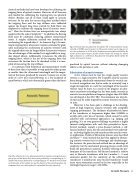
accelerating the trapped object . As shown in Fig.2, the max-
imum trapping force of acoustic tweezers estimated by grad- ually increasing the acceleration of acoustic tweezers until the trapped object can no longer follow the acoustic tweezers. One of advantages of this method is its applicability to irreg- ular shaped objects. Additionally, it measures the effective trapping force, which is the net of the trapping force that overcomes the friction force. Its drawback is that it is inca- pable of measuring the trap stiffness.
In summary, both theoretical and measurement results to date show that it is possible to trap particles either greater or smaller than the ultrasound wavelength and the magni- tude of the forces produced by acoustic tweezers are on the order of a few tens of picoNewtons to a few hundreds of nanoNewtons, which are substantially greater than the forces
produced by optical tweezers without inducing damaging effects to the particles or cells.
Fabrication of acoustic tweezers
A few criteria must be met for a high quality acoustic tweezer, i.e., high sensitivity, low f-number, and the acoustic beam being cylindrically symmetrical about the vertical axis. A critical recognition was that in order to accurately trap a single microparticle or a cell, the wavelength of the acoustic tweezer must be short. As a result of the progress of ultra- sonic transducer technology that has been made, recently an acoustic tweezer platform at frequency higher than 200 MHz was developed at the NIC TRC. The minimum size of parti- cle that may be stably trapped by acoustic tweezers was down to 1μm.
However, it has been quite a challenge in the develop-
ment of high frequency acoustic tweezers with acceptable
trapping performance. The thickness of piezoelectric layers
of the transducers at frequencies higher than 100MHz, is
usually only a few tens of microns, which cannot be easily
achieved with conventional approaches, e.g. lapping and
grinding. It is an even greater challenge to produce a highly
focused configuration with such thin piezoelectric layers.
Several methods, namely a press-focused method, a self-
focused method12 and a lens-focused method were undertak-
en to develop highly focused transducers for acoustic tweez-
er applications. Details of fabrication process were described
12-14
elsewhere . Each method that has been applied to fabricat-
ing acoustic tweezers has its advantages and disadvantages. For instance, the press-focused method has an advantage of simplicity, but the mechanical pressing process could easily break the piezoelectric material, therefore affecting the per- formance of the transducer. Self-focused method is relative easy to fabricate transducers with low f-number (~ 1) and consistent quality, but the sensitivity of the self-focused transducers is usually poor. Lens-focused transducers would incur extra attenuation caused by the lens especially in the ultrahigh frequency range (>100 MHz).
Fig.2. Demonstration of a polystyrene microsphere (90 m mean diameter) manip- ulated by a 70 MHz acoustic tweezer. (a) The acoustic tweezer was moving at a rel- ative low acceleration (a =5,000 m/s2), the polystyrene microsphere could follow the motion of the acoustic tweezer. (b) The acoustic tweezer was moving at a relative high acceleration (a =5,500 m/s2), the polystyrene microsphere failed to follow the motion of the acoustic tweezer.
Fig.1 The radiation force on a sphere generated by momentum exchange between a pair of rays and the objects; Fa is the net force produced by a corresponding ray ‘‘a’’ and Fb is the net force produced by a corresponding ray ‘‘b’’. Two forces were resolved in the direction of the incident ray and the direction of the intensity gradient, the component forces are scattering force Fs and gradient force Fg, respectively.
Acoustic Tweezers 11
