
Page 29 - Fall2013
P. 29
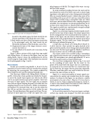
  Figure 5 Single bent-type model with sliding blocks (Model C)
located in the palatal region, but back vowels do not.
Vertical movement of the block takes care of this.
2) Back vowels must have a block for tongue constriction in the pharyngeal cavity, but front vowels do not.
Horizontal movement of the block takes care of this.
3) Diagonal protrusion of the tongue dorsum is neces-
sary for the vowel /u/.
4) An extra block at the mouth end is necessary for lip
rounding.
Figure 5 shows a picture of this single bent-type model
with sliding blocks. As shown in this figure, there are four sliding blocks. Figure 6 shows the configuration for all five vowels using this single model. (The front plate was removed for the photographs in Figs. 5 and 6.)
Measurements
Sounds were recorded using Models A, B and C for the formation of the five vowels and these sounds were analyzed by inspecting the spectrograms. The sounds produced by these models are also used for informal listening tests.
Two Bent-type Models with Sliding Blocks (Models A and B). A driver for a horn speaker was attached to the glot- tis end of the model. Input signals were fed into the driver unit via an audio interface and a power amplifier. There were two types of input signals. The first signal was an impulse train with an original sampling frequency of 16 kHz; later, the sampling frequency was increased to 48 kHz. Its fundamen- tal frequency, f0, increased from 100 to 125 Hz within the first 100 ms, and then decreased to 100 Hz within the next 200 ms. The total duration of this signal was 300 ms. The sec- ond type of input signal was a swept-sine signal with a sam-
pling frequency of 48 kHz. The length of the swept- sine sig- nal was 65536 samples.
To avoid unwanted coupling between the neck and the area behind the neck of the driver unit and to achieve high impedance at the glottis end, a close-fitting metal cylindrical filler was inserted inside the neck. A hole in the center of the metal filling with an area of 0.13 cm2 was created.The output sounds were recorded using a microphone from the sound level meter and an audio interface with a sampling frequency of 48 kHz. The microphone was placed approximately 20 cm in front of the output end in a sound-treated room (Fig. 4). The signals recorded were synchronously averaged multiple times to gain the signal-to-noise ratio.
Figure 5 is a sound spectrogram of output signals record- ed with the first type of input signal. The output signals from the five configurations were concatenated for this analysis. As shown in this figure, one can observe clear formants, espe- cially the first and second formants (F1 and F2) in the lower frequency region. The five vowels were clearly distinguish- able during an informal listening test.
A Single Bent-type Model with Sliding Blocks (Model C). A driver unit for a horn speaker was again attached to the glottis end of the model; a close-fitting metal cylindrical filler was also used. The first input signal for Models A and B was fed into the driver unit via a USB audio amplifier .
The output sounds were recorded using a microphone and a digital audio recorder with a sampling frequency of 48 kHz. The microphone was placed approximately 15 cm in front of the output end in a sound-treated room.
The vocal-tract configuration shown in Fig. 3 was used for the recordings of each vowel. For the vowel /u/, the groove of the main block (the largest one) was, unfortunate- ly, connected to the central hole that was created when slid- ing the block for the tongue dorsum protrusion diagonally. Therefore, small thin plates were used to block the two con- nections (the short red lines in Fig. 3).
Figure 6 is a sound spectrogram of output signals con- catenated for this analysis and recorded from the five config- urations. As shown in this figure, we can observe a similar spectrogram to the one in Fig. 5. However, F1 is less clear in vowels /u/ and /o/. From an informal listening test, vowels /i/, /e/ and /a/ were clearly heard. The vowels /o/ and /u/ had rea- sonable quality but were a bit less intelligible.
Discussion and conclusions
In the activities reported in the present paper, mechani- cal bent-type models were designed. Two bent-type models
  Figure 6. Single bent-type model (Model C) for five vowels
28 Acoustics Today, October 2013
