
Page 42 - \Winter 2015
P. 42
Acoustic Cloaking
in the green part is like that of Figure 1, with faster vertical wave speed and unchanged horizontal speed. In the yellow section the principle axes for the wave speeds are rotated from the vertical and horizontal, one faster and the other slower than the background speed. The difference in proper- ties is evident from the ray paths (Figure 2). Each ray is the transformation of the straight rays in the virtual region, the dotted lines in Figure 2. As long as the bottom surface of the carpet cloak is the same as the virtual region, the net effect of the carpet cloak is to make the cloaked region appear to be infinitely thin. The general carpet cloak transformation (Figure 3 (a)), is suitable for hiding in "plain sight" against a flat surface. But in the absence of a flat boundary to provide camouflage, TA must reduce the combined cloak and the cloaked region into an infinitesimally small scatterer with zero scattering cross-section.
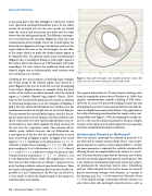
Cloaking in free space requires a vanishing target strength; the virtual image of the cloaked region must shrink to a point (Figures 3 (a), (c)). As in the 1D case, the TA mapping is not unique. Figure 4 shows an example where the outer surface of the cloak is an oblate spheroid, while the cloaked region is a prolate ellipsoid (egg shaped) (Norris, 2008). Some of the transformed region must be rotated in addition to stretching/compression as in the examples of Figures 1 and 2. The rays shown for horizontal wave incidence are the transformed versions of straight lines in the virtual domain. The rays around the central cloaked region, which is the im- age of a point in the virtual domain, must have infinite wave speed. Conversely, the wave speed perpendicular to the in- ner boundary is zero, which explains the sharp curvature of the rays near the "stagnation" point. Thes extreme effects, infinite speed, infinite slowness and ray bifurcation, are a consequence of the fact that the transformation is much more severe than in Figures 1 and 2. In Figure 1 the virtual region 0 < x < 1 transforms to the physical one 1−f < x' <1.
Figure 4. Ray paths through a non-radially symmetric cloak. The solid curves are the inner and outer surface of the cloak.
The original motivation for TA and acoustic cloaking came from the remarkable observation of Pendry et al. (2006) that singular transformations provide cloaking of EM waves. However, in a sense TA preceded cloaking, because the idea of mapping the acoustic wave equation has been used for de- cades in simplifying numerical problems. One application is the surface flattening transformation for rough surface scat- tering (Beilis and Tappert, 1979); by mapping the rough sur- face to a flat one the numerical geometry becomes simpler to mesh, at the expense of an inhomogeneous wave equation and more complicated boundary conditions.
Anisotropic Density or Stiffness?
How can acoustic anisotropy be achieved in practice? It is not observed in natural acoustic fluids where wave propa- gation depends on density ρ and compressibility C. At least one more parameter is required; this could be introduced by allowing density or compressibility to be tensors (i.e., matri- ces). Tensorial density means that the force per unit volume ρa is not necessarily aligned with particle acceleration a. This is not ruled out on fundamental grounds and in fact a physi- cal mechanism for anisotropic inertia exists. Schoenberg and Sen (1983) showed that the inertia tensor in a layered fluid is transversely isotropic with elements <ρ> normal to the layering, and 1/<ρ-1> in the transverse direction, where <.> is the spatial average. Anisotropic effective density can arise from other sub-wavelength microstructures, such as
Consider a simple linear mapping, x' = 1−f + f x. The analo- In TEXT Equations - Norris Article
gous mapping in 2 or 3-dimensions is r' = 1−f + f r where 0 < r < 1 and 1−f < r' < 1 define the virtual and physical radii.
!!!
flects the fact that a finite area or volume is compressed to a point, leading to infinite values of speed and slowness. These
possible in 2 and 3 dimensions,𝐶𝐶𝑝𝑝th=e−𝛁𝛁b.e𝐯𝐯st one can achieve is
a "near cloak" in which the cloaked region is the image of a
𝑓𝑓 𝑑𝑑𝑑𝑑 where d = 2 or 3 is the dimension (Norris, 2008). The singularity as r→0 re-
Volume elements transform as 𝑑𝑑𝑉𝑉! = 𝑟𝑟! 𝑟𝑟
are clearly unattainable implying that the perfect cloak is im-
small but finite area/volume.
𝛁𝛁. 𝜌𝜌!!𝛁𝛁𝑝𝑝 −𝐶𝐶𝑝𝑝=0
40 | Acoustics Today | Winter 2015
〈𝜌𝜌!! 〉
𝜌𝜌𝐯𝐯 = −𝛁𝛁𝑝𝑝
