
Page 53 - Fall_DTF
P. 53
cause the grating lobes of the subarrays do not overlap when 8) comparison oi coprime and ULA geomeiries
M and N are coprime.
on on 0 I0 o 0: 0 no in M=7,N=9
Since the early work of Berman and Clay (1957), many re- °°'°°'°°'°°'°°'°°'°°'°°'°°'°° M=2, N=3
searchers have explored using multiplicative processing ULA
to mitigate aliasing in interleaved sparse arrays. Although 40 —2o 40 0 I0 20 30
this approach has been effective in many applications, it 1
has some disadvantages. One downside of multiplicative i h) 395". and Fgwgr pmems [gr M:7_ N=9 anq u|_A
processing is that it is not guaranteed to produce positive
definitepower spectral estimates (Adhikari and Buck, 2017).
Another disadvantage of multiplicative processing is that it
requires time averaging to reduce the impact of cross terms. 0 5
As described by Pedinoff and Ksienski (1962), cross terms
arise when the inputs to the subarrays contain more than .
. _ _ _ r-.:.=.c==~=‘-.5 =f ‘ 5 11.; =e.=‘ Lgs,-1 2.5..
one signal. When the arriving signals are uncorrelated, av- D i, ,i_'. | ,l. -5 1 ii «. = l 5 I ii x": . ._ i- I E= | ‘E’
eraging the multiplicative processor output reduces cross- l. l,l l
term interference. Unfortunately, there are some applica- ‘ -7 5 5" ‘ 5 ii 7 ‘ ’= F 5 E‘ 3 5‘ ’=
tions where limited data are available for averaging due to “».‘“’ En“ :".....“"—l'i-ml"5‘ ' ' "_in"“
source motion or other environmental variability. Recently, '0 5 i ii 5 0 U 5 i
both Di Martino and Iodice (2015) and Liu and Buck (2015) u:CO5lu)
proposed an alternative algorithm that computes the mini- _ _
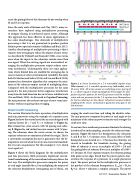
mum oiihe subway oiiiiiiiis iiisieaii of miiiiipiyiiig iimii Figure 2. u: Serisnr lnmtwns /er u 7. 9 imextended eepmne army
. _ _ . (uue crosses), u 2, 3 extended cnprime army (red circles), und u
Compared with the multiplicative processor for the same . .
_ _ 63—sensar ULA. All urruys ussume un underlying sensor spacing af
8e0metrY— the mm Processor better suppresses Interference d = 1, which is equal ta u hulfwuvelengthfm the examples. b: Cam—
away from the look direction due to its lower sidelobe levels Pu,-{sun gfpgwgr Pufiernsfgy the 1/LA P,-Wes”, and the muztipig,
(Liu and Buck, 2018). As discussed in Coprime Processing, mtive and min pracessarsfar the 7. 9 cnprime urruy. Beumputtems
the min processor also reduces one type of cross-term inter- f”"_the_tW” 5“b‘""“}’5 ‘"9 “'50 5lf‘7W"- A” P‘'“‘?’'”5 “5_5""‘9_""_‘f”"'“
imme wiiimiii requiring time avmgiiig weighting ef the serisnrs narmalized ta guarantee unity gum in the
lank directinn.
Gap!-ima Processing
This section illustrates the basic operation of multiplicative eraging the result over time, and taking the absolute value.
and min processors using the example of a coprime array The min processor computes the power at each angle as the
Figure 2a shows the sensor layout for an array designed with minimum of the subarray power estimates and averages the
coprime factors M = 7 and N = 9. Subarray A (Figure 2a, result over time.
blue crufses) has seven_ sensors 9d ‘P““‘3_““d subap To see how these nonlinear processors eliminate the aliasing
ray B (Figure 2a’ red antes) has “me sensors wnh 7d spao introduced by undersampling, consider the subarray beam-
ing. The subarrays share the center sensor. As shown, the .
_ _ _ _ _ _ patterns. Figure 2b shows the beampatterns for subarrays
coprime subarrays are symmetrical about the origin. This is A and B of the 7, 9 coprime array The main iobes of both
a convenient assumption because it guarantees that the be- _
_ beampatterns are located at u — 0 because the subarrays are
ampatterns are real when the arrays are steered to broadside, . . . .
b _ _ _ F ih_ 1 d M h_ h steered to broadside. For broadside steering, the grating
_ In “ ‘S nit a requflemmt‘ or 15 exam? 6 T 2‘ W ‘C lobes of subarray A occur at multiples of }\/Nd = 2/9 and
'5 Se‘ eq“ lo 1‘ the grating lobes of subarray B occur at multiples of A/Md =
Figure 3 shows the block diagrams for the multiplicative 2/7. Because M, N are coprime integers, the subarray grating
and min processors. Both processors implement conven- lobe peaks never align. Recall that the power pattern char-
tional beamforming of the narrowband subarray data as the acterizes the response of a processor to a single planewave
first step. The multiplicative processor computes the power input. The power pattern for the multiplicative processor is
at each angle (specified by u“) by multiplying the outputs of the product of the subarray beampatterns: Pm_iii(u) = BA(u)
the subarray bea.mformers (conjugating one of them), ava Bii*(u), where 40» indicates a complex conjugate. The power
Fall 2012; | Acoustic: Triduy | 51
