
Page 57 - Spring 2018
P. 57
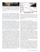
  Figure 7. A musician plays a flute (a). Schlieren visualizations (b and c) of a jet blowing an experimental system with comparable ge- ometry. A nozzle (top right) directs a jet across the embouchure hole toward the edge on the opposite side. In b, vertical deflections of the jet are seen. In c, vortices are shed on alternate sides. b and c courtesy of Benoit Fabre.
Some are used only for trills and fast passages; others are used for subtle effects of pitch and timbre. Some fingerings produce two or more resonances that are not related as fun- damental and harmonic. In this case, it is sometimes possible to play a superposition of notes at the different resonances, usually at a low sound level. These chords are called multi- phonics in the modern solo and chamber music repertoire.
Sound Production with an Air Jet
The directional instability of a jet is demonstrated by a rising plume of cigarette smoke in still air. A jet deflects alternately in lateral directions and, after a while, sheds vortices. In the air-jet family, a narrow, high-speed jet is blown across a hole in the instrument toward a fairly sharp edge, the labium. In flutes, in the end-blown shakuhachi, and in panpipes, a high-speed jet emerges from between the player’s lips. In the recorder and ocarina, a tiny duct called a windway guides the jet to the labium, making it easier to sound a note.
At the labium, downward deflections of the jet flow into the bore and upward deflections flow outside the instrument (Figure 7). With a suitable phase, standing waves with large flow amplitudes at the embouchure hole can entrap the jet in a feedback loop that causes it to be directed alternately into and outside the bore, thus maintaining the amplitude of standing waves in the bore and, in the starting transient, increasing it. The frequency of spontaneous deflections of the flute jet increases with jet speed, so successively faster jet speeds (typically tens of meters per second) excite succes- sively higher resonances via a mechanism involving several subtleties (Fletcher and Rossing, 1998; Auvray et al., 2014). The different possibilities of lip aperture and jet speed, angle, height, and length give the player a range of parameters to control pitch, loudness, and timbre. For example, the pitch can be lowered significantly by rolling the instrument so that the lower lip occludes more of the embouchure hole, which increases the end effect. Turbulence produces a broadband signal (we can hardly call it “noise” in this context), which is an important part of timbre, especially for panpipes.
Figure 8. Sketch plots of airflow (U) past a clarinet reed as a function of blowing pressure (P). Inset: the mouthpiece. The player rests the reed on the lower lip, the upper teeth on the mouthpiece, and seals the lips around the mouthpiece to blow. Blue curve, lip force of 1 newton; red curve, lip force of 2 newtons. See text for details. After Dalmont and Frappé (2007).
Sound Production with Reeds
In reed instruments, one or a pair of reeds are deflected by the varying pressure in the bore so as to modulate the airflow into the instrument. For clarinets and saxophones, the single reed is fixed on a mouthpiece (Figure 8) and bends like a cantilever to produce an oscillating aperture. Double-reed instruments (e.g., oboe and bassoon) have two symmetri- cal and curved blades that alternatingly flatten and curve to close and open the aperture (Figure 1, d and e). Clarinet and saxophone reeds are damped by the player’s lower lip; the double reeds of the oboe and bassoon by both lips.
Consider the clarinet mouthpiece in Figure 8. Starting from zero, the blowing pressure (P) is gradually increased and the steady flow (U) past the reed is recorded. For now, neglect standing waves inside the mouthpiece. Initially, the airflow increases rapidly with increasing P; if all the air’s kinetic energy is dissipated in downstream turbulence, we expect, from Bernoulli’s equation, U ∝√P. At large P, however, the pressure closes the reed against the mouthpiece and the flow must go to zero and does so at lower P if we increase the lip force (Figure 8, red curve).
Consider a point on the right side of the curve, where U decreases with increasing P. For steady flow, the ratio P/U is positive (inverse slope of dashed line); the mouthpiece is like an acoustic resistance, taking power out of the incom- ing high-pressure air. But for small acoustic signals, ∂P/∂U (solid tangent) is negative; the mouthpiece is a negative resistance, inputting acoustic power to the clarinet. At the peak of the curves in Figure 6, the bore impedance is resis- tive, and if its resistance is larger than −∂P/∂U, then the reed
  Spring 2018 | Acoustics Today | 55
