
Page 52 - Winter2018
P. 52
Advancements in Thermophones
width. This is primarily the result of a lack of mechanical moving parts that always have accompanying passive struc- tural resonances. Normally, these resonances are “pushed out” of the band of interest through a combination of ma- terial choice and appropriate sizing of structural parts. For thermophones used as a precision source of sound, the only dimensions of concern that would limit bandwidth are those of the cavity encasing the thermophone and microphone element being calibrated. It remains today that one of the most attractive features of thermophones is that their acous- tic response is largely decoupled from any mechanical parts.
Thermophones saw utility as a precision source of sound but were never widely used for any other purpose due to their poor efficiency compared with the electrodynamic loud- speaker and other more conventional transduction sound sources. As with some other transducers, thermophones are also hindered when it comes to reproducing arbitrary wave- forms due to their intrinsically nonlinear transduction. The acoustic response is quadratic with respect to the driving volt- age or current and requires a DC bias to linearize the response. Similar to what occurs in a variable reluctance transducer, this bias current continuously generates excess heat and reduces efficiency. Other modern conventional signal-processing techniques such as amplitude modulation, pulse width mod- ulation, and pulse amplitude modulation can be used as well to rectify arbitrary signals. Bouman et al. (2016) provide a comparison of their thermophone’s efficiency with a biased input signal versus an amplitude-modulated one. Even with rectified signals, however, the various frequency components of an arbitrary input signal will still generate corresponding heterodynes as well as second harmonics. Although typically undesired, such nonlinearities can be exploited to probe ma- terial properties (Heath and Horsell, 2017).
Modern Thermophones
Relatively few articles concerning thermophones were pub- lished after the 1940s until Shinoda et al. (1999), inspired by photoacoustic studies on porous silicon, presented a porous doped silicon thermophone for ultrasonic emission. Inter- est grew substantially after Xiao et al. (2008) from Tsinghua University reported a flexible thermophone with an active element composed of a CNT sheet. CNTs are nanoscopic or nanoscale cylinders of carbon atoms arranged in a hexago- nal lattice (much like a piece of wrapped chicken wire) that can have exceedingly high aspect ratios.
A
B
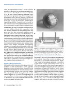
Figure 2. A: thermophone on its backplate used as a precision source of sound for microphone calibration (Ballantine, 1932). B: a schematic of an assembled thermophone and microphone from Sivian (1931). T, thermophone active element; D, electrostatic microphone diaphragm. Images reprinted from Nokia Bell Laboratories, with permission.
For example, CNTs used in thermophones have a diameter on the order of 10 nm (about 1/10,000 the thickness of a human hair) but are hundreds of microns in length. A CNT “sheet” useful for thermophone applications is made from a CNT “forest” (a highly oriented dense vertical array of CNTs) made by a process called chemical vapor deposition (CVD). The CVD process for growing the CNTs now used in thermophones was adapted by Zhang et al. (2005). Catalyst nanoparticles are deposited on a silicon wafer and individual CNTs grow vertically from these catalyst particles during the CVD process as a heated feedstock gas is passed over the wa- fer. With careful adjustment of various growth parameters, the edge of the resulting forest can be mechanically pulled into a less dense porous sheet of horizontally aligned CNTs (Figure 3). The roughly 50-μm-thick CNT sheet can be con-
50 | Acoustics Today | Winter 2018
