
Page 14 - Spring2019
P. 14
Acoustic Systems for Defense
Compiling the Air Picture While at Depth
During World War II, aircraft equipped with centimeter- wavelength radars accounted for the bulk of Allied defeats of U-boats from 1943 to 1945. U-boats spent most of their time surfaced, running on diesel engines and diving only when attacked or for rare daytime torpedo attacks (Lans- ford and Tucker, 2012).
In 1987, a series of at-sea experiments using Australian submarines and maritime patrol aircraft demonstrated the detection, classification, localization, and tracking of aircraft using a towed array deployed from a submarine (Ferguson and Speechley, 1989). The results subsequently informed the full-scale engineering development of the Automated Threat Overflight Monitoring System (ATOMS) for the US Navy submarine force. ATOMS offers early warning/long-range detection of threat aircraft by submerged submarines via towed arrays (Friedman, 2006).
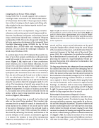
In a seminal paper, Urick (1972) indicated the possible exis- tence of up to four separate contributions to the underwater sound field created by the presence of an airborne acoustic source. Figure 3, left, depicts each of these contributions: direct refraction, one or more bottom reflections, the eva- nescent wave, and sound scattered from a rough sea surface. When the aircraft flies overhead, its radiated acoustic noise travels via the direct refraction path where it is received by a hydrophone (after transmission across the air-sea interface). Now, the ratio of the speed of sound in air to that in water is 0.22; at a critical angle of incidence (c ) = 13°, the black ar- rows in Figure 3 (the incident ray in air and the refracted ray along the sea surface) depict the propagation path of a criti- cal ray. The transmission of aircraft noise across the air-sea interface occurs when the angle of incidence is less than c (Figure 3, red arrows). For angles of incidence greater than c , the radiated noise of the aircraft is reflected from the sea surface, with no energy being transmitted across the air-sea interface (Figure 3, blue arrows).
The reception of noise from an aircraft via the direct path relies on the aircraft being overhead. This transitory phe- nomenon lasts for a couple of seconds; its intensity and du- ration depend on the altitude of the aircraft and the depth of the receiver. Submariners refer to the overhead transit as an aircraft “on top.” Urick (1972) estimated the altitude of the aircraft by measuring the intensity and duration of the acoustic footprint of the aircraft. An alternative approach is to measure the variation in time of the instantaneous frequency corresponding to the propeller blade rate of the
Figure 3. Left: contributions made by an acoustic source in the air to the sound field at a receiver in the sea. From Urick (1972). Right: ray paths for a bottom bounce (green arrows), direct refraction (red ar- rows), critical angle where the refracted ray lies along the sea surface (black arrows), and sea surface reflection (blue arrows). See text for further explanation.
aircraft and then extract tactical information on the speed (using the Doppler effect), altitude (using the rate of change of the instantaneous frequency), and identification (from the source/rest frequency of the blade rate) of the aircraft (Fer- guson, 1996). For a submariner, the upside of an aircraft on top is identification of the aircraft and its mission profile by processing the output of a single hydrophone without giv- ing away the position of the submarine; the downside is that there is no early warning.
The long-range detection of a submarine relies on reception of the radiated noise from the aircraft after undergoing one (or more) reflections from the seafloor (Ferguson and Speechley, 2009). The intensity of the noise from the aircraft received via direct refraction is considerably stronger (by 20 to 30 dB) than for propagation involving a seafloor reflection, so a towed ar- ray is required to detect the Doppler-shifted propeller blade rate (and its harmonics) and to measure its angle of arrival (bearing). A submarine with its towed array deployed has many minutes warning of an approaching aircraft. In Figure 3, right, the green arrows depict a bottom bounce path that enables the long-range detection of an aircraft.
Estimating the Instantaneous Range of a Contact
The towed-array sonar from a submarine is only able to mea- sure the bearing of a contact. To estimate its range, the subma- rine must undertake a maneuver to get another fix on the con- tact and then triangulate its position. This process takes tens of minutes. Another approach is to use wide-aperture array sonar, which exploits the principle of passive ranging by wave front curvature to estimate the bearing and range of the contact at any instant, without having to perform a submarine maneuver (see Figure 4, left). The radius of curvature of the wave front equates to the range. Measurement of the differences in the ar- rival times (or time delays τ12 and τ23) of the wave front at two
12 | Acoustics Today | Spring 2019
