
Page 18 - Spring2019
P. 18
Acoustic Systems for Defense
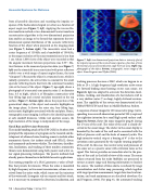
from all possible directions and recording the impulse re- sponse of the backscattered signal (or echo) as a function of aspect angle (see Figure 7, left). Applying the inverse Ra- don transform method or two-dimensional Fourier transform reconstruction algorithm to the two-dimensional projection data enables an image to be formed that represents the two- dimensional spatial distribution of the acoustic reflectivity function of the object when projected on the imaging plane (see Figure 7, bottom right). The monostatic sonar had a center frequency of 150 kHz and a bandwidth of 100 kHz, so the range resolution of the sonar transmissions is less than 1 cm. About 1,000 views of the object were recorded so that the angular increment between projections was 0.35°. Dis- tinct features in the measured projection data (see Figure 7, left) are the sinusoidal traces associated with point reflectors visible over a wide range of aspect angles (hence, the term “sinogram”). Because the object is a truncated cone, which is radially symmetric, the arrival time is constant for the small specular reflecting facets that form the outermost boundary (rim at the base) of the object. Figure 7, top right, shows a photograph of a truncated cone practice mine (1 m diameter base, 0.5 m high), which is of fiberglass construction with four lifting lugs and a metal end plate mounted on the top surface. Figure 7, bottom right, shows the projection of the geometrical shape of the object and acoustic highlights on the image plane. It shows the outer rim, four lifting lugs, and acoustic highlights associated with the end plate. Hence, tomographic sonar imaging is effective for identifying mines at safe standoff distances. Unlike real aperture sonars, the high resolution of the image is independent of the range.
Naval Base and Port Asset Protection
The suicide bombing attack of the USS COLE in October 2000 prompted the expansion of a program on the research and de- velopment of advanced mine-hunting sonars to include other asymmetric threats: fast inshore attack craft (FIAC), divers, and unmanned underwater vehicles. The detection, classifica- tion, localization, and tracking of these modern asymmetric threats were demonstrated using both passive and active so- nar signal-processing techniques. The passive methods had already proven themselves in battlefield acoustic applications.
The rotating propeller of a FIAC generates a wake of bub- bles that persists for minutes. When the wake is insonified by high-frequency active sonar transmissions, echoes are re- ceived from the entire wake, which traces out the trajectory of the watercraft. Insurgents rely on surprise and fast attack, so it is necessary to automate the detection, localization, and
Figure 7. Left: two-dimensional projection data or intensity plot of the impulse response of the received sonar signal as a function of time (horizontal axis) and insonification angle (vertical axis). Right: top, photograph of the object; bottom, tomographic sonar image of the object. From Ferguson and Wyber (2005).
tracking processes because a FIAC attack can happen in as little as 20 s. A high-frequency high-resolution active sonar (or forward-looking mine-hunting sector scan sonar; see Figure 8, top) was adapted to automate the detection, local- ization, tracking, and classification of a fast inshore craft in a very shallow water (7 m deep), highly-cluttered environ- ment. The capability of the system was demonstrated at the HMAS PENGUIN naval base in Middle Harbour, Sydney.
A sequence of sonar images for 100 consecutive pings (corre- sponding to an overall observation period of 200 s) captured the nighttime intrusion by a small high-speed surface craft. Figure 8, bottom, shows the sonar image for ping 61 during the U-turn of the craft. The wake of the craft is clearly ob- served in the sonar image. The clutter in the sonar display is bounded by the wake of the craft and is associated with the hulls of pleasure craft and the keels of moored yachts. The high-intensity vertical strip at a bearing of 6° is due to the cavitation noise generated by the rapidly rotating propeller of the craft. In this case, the receiver array and processor of the sonar act as a passive sonar with cavitation noise as the signal. This feature provides an immediate alert to the pres- ence of the craft in the field of view of the sonar. The sonar echoes returned from the wake (bubbles) are processed to extract accurate range and bearing information to localize the source. The number of false alarms is reduced by range normalization and clutter map processing, which together with target position measurement, target detection/track ini- tiation, and track maintenance are described elsewhere (Lo and Ferguson, 2004). For ping 61, the automated tracking
16 | Acoustics Today | Spring 2019
