
Page 56 - WINTER2019
P. 56
Second Century of Electroacoustics
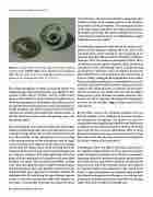
Figure 1. An open carbon microphone capsule showing the internal carbon granules (middle right) and the flexible pressure diaphragm (left). The post at the center of the diaphragm transfers the acoustic pressure to the carbon granules. From bit.ly/2Ul6lrK
The carbon microphone is simply an enclosed capsule con- taining loosely packed carbon granules (e.g., Figure 1). This capsule is often called a “button,” and the carbon micro- phone is often called the carbon button microphone or just the button microphone in the literature. The carbon granules are somewhat electrically conductive, and their package has a flexible membrane that allows acoustic pressure to cyclically compress the thickness and compact the carbon particles so that the electrical resistance across the package varies with the pressure signal.
The early telephone system operated without the active ampli- fication we understand today. The circuit did, however, have a constant voltage source that created a nominal circuit cur- rent. The resistance of the transmission line was constant, so the varying resistance of the microphone caused a signal current variation to be imposed on the otherwise constant current from the voltage source. At the receiving end of the transmission line, the varying current passed through a coil in a magnetic earphone. The audio signal from the micro- phone end was reproduced in the earphone with reasonable loudness and clarity. The sensitivity, bandwidth, internal noise level, and signal distortion would be considered poor by present listeners. But it was possible to transmit the lim- ited bandwidth voice signal for several miles through the telephone cable. By transferring the signal through repeater circuits to successive transmission cables with separate cur- rent loops, it was possible to transmit the signal over much
longer distances. The repeater included is a magnetomechan- ical driver similar to the earphone drivers in the telephone and another carbon microphone. This mechanical actuator in the input current loop drives the carbon microphone in the output current loop. The constant voltage source in each current loop provides the power to enable the gain in signal amplitude across the repeater.
Considerable progress was made beyond the carbon micro- phone and the magnetic earphone. By 1925, most of the currently known major transducer types operating in air had been described. This includes the dynamic microphone (Siemens, 1874), the condenser microphone (Wente, 1922), the balanced armature speaker (Egerton, 1921), and moving coil speakers (Rice and Kellogg, 1925). Transducers that could operate underwater were investigated during and after World War I (see the article by Sustick in this issue of
Acoustics Today). Among the first hydrophones was a carbon button microphone packaged in a watertight housing with a flexible waterproof window to allow acoustic pressure to compress the carbon granules. In addition, the first piezo- electric transducers for underwater use were developed using quartz crystals. The basic transducer structures were known, but better materials and improved design meth- ods were not yet available. Figure 2 shows some of these early devices.
By the 1930s, vacuum tube electronic amplifiers were suf- ficiently available so that textbooks on acoustics described the operation of microphones and speakers in ways that assumed electronic amplification would be used. Books such as Applied Acoustics (Olsen and Massa, 1936) in the United States and The New Acoustics (McLachlan, 1936) in Great Britain described the state of practice between the two World Wars. This article takes this time period as the starting point for the first century of electroacoustics.
Developments from two different directions gave birth to the significant improvements in device and system perfor- mance during the twentieth century. The first is consistently improving methods of performance analysis and prediction of acoustic devices and systems. Methods of hand calcula- tion in the first half of the twentieth century were replaced by computer analysis since midcentury. The second major theme is improved materials and manufacturing methods that allowed each generation of designers to see designs and performance in the last part of their careers that was unimag- inable when they entered the technology area.
56 | Acoustics Today | Winter 2019
