
Page 59 - WINTER2019
P. 59
ABC
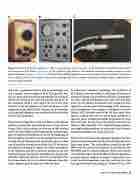
Figure 3. Much of the laboratory equipment c. 1950 is recognizable by current researchers. a: The Hewlett-Packard 200CD audio oscillator was introduced in 1952. From bit.ly/30Kk8u3. b: The capabilities of this Tektronix 535 dual-beam oscilloscope would be welcome in current acoustics laboratories. From bit.ly/2Zzv1ld. c: The Brüel & Kjær (B&K) standard measurement microphones were introduced in 1958. Shown here is a B&K 4134 0.5-inch microphone. The cylindrical package behind the microphone diaphragm cartridge contains a cathode follower (vacuum tube) preamplifier.
that stores a permanent electric field in an analogous way that a magnet stores a magnetic field. The potential ben- efits of a good electret had been hypothesized, but no good electret materials had ever been identified or produced. In fact, Gutmann (1948, p. 470) reports the use of very poor electrets in the microphones of captured Japanese radio equipment during World War II. However, the microphones in the captured equipment were nonfunctional because their electrets had discharged.
The electret developed by Sessler and West is a thin film of polymer material that permanently stores a large electric charge (West, 1988, provides an overview of that develop- ment). The electret film can be bonded inside the electrostatic gap of a condenser microphone or used as the diaphragm of that microphone. In either case, the charged electret creates a strong electric field across the electrostatic gap and elimi- nates the need for external electrical bias. By 1975, the electret microphone had begun to replace the carbon microphone in the telephone and other consumer equipment and also replaced magnetic and ceramic microphones in hearing aids and other miniature earpieces. Electret microphones were the obvious choice for use in cellular telephones when that market began to grow through the 1980s and 1990s.
In underwater transducer technology, the availability of PZT ceramic materials enabled a wide range of underwater transducer designs that provide the full suite of capabilities for surface ship and submarine sonars. Most of this develop- ment was not publicly documented, but enough has been reported to provide some understanding of the magnitude of the developments. For example, a retrospective article by Hueter (1972) describes some of the US Navy sonar devel- opment. Among these was the use of large cylindrical or spherical arrays including hundreds of piezoelectric trans- ducer elements. By the end of this period, standard texts (Wilson, 1985; Stansfield, 1991) included design guidance and simple analysis methods to understand these elements and their performance in arrays of any size.
Hueter (1972) mentions some significant problems that were discovered and eventually solved in the development of the large sonar arrays. “The real problem occurred in the early 1960s with two active low-frequency arrays built for the ARTEMIS and the LORAD programs. Both arrays demon- strated local hot spots where the effective element impedance assumed negative radiation resistance values which were traced to mutual impedance terms that, until this time, had been ignored by most array designers” (Hueter, 1972, p. 1029).
Winter 2019 | Acoustics Today | 59
