
Page 52 - Winter 2020
P. 52
ROOM-ACOUSTIC AURALIZATION
resulting in secondary image sources that are again image reflected against all the surfaces. This represents a recursive process until termination criteria are met, such as reflection order or energy threshold. The resulting image sources are essentially secondary sources, each of which carries a reflection history. The distance from the image source to a receiver is used to determine the actual reflection path length. Figure 4 illustrates schematically this recursive construction of the image sources in a two- dimensional case. Four first-order reflections along with six second-order reflections are illustrated (actually there are eight second-order ones). Generally, the number of image sources up to Mth-order reflections is given by
for N surfaces. The image-source method yields exact solutions for rectangular rooms and ideally hard surfaces, although in real rooms, there is always some modeling error due to real material properties and lacking modeling of edge diffraction.
Borish (1984) extended the image-source method for arbitrary room shapes, allowing a high flexibility of geometry. The recursive construction of reflections is the same as that of rectangular rooms, yet additional checks need to be pursued. For example, if the previous reflector completely covers the current reflector, there is no need to create a new image source. All of these image sources
are independently computed from the receiver position. Thus, the resulting image sources are valid for the entire room. From the viewpoint of the auralization, this means, that all the image sources can be precomputed for a given
sound source.
The last step is checking the “visibility” of each image source to a given listener location. This step needs to be repeated whenever the receiver moves, and it creates a specular reflection path from the source to the receiver, as illustrated in Figure 5a. To pass the test, the path must reach all the reflecting surfaces within the room boundaries and may not be obstructed by any other surface. The sum of the contributions of all visible image sources leads to the room impulse response. For binaural auralization, a binaural receiver in the form of a HRTF is straightforwardly incorporated, resulting in one pair of binaural room impulse responses. The source directivities can be incorporated by image reflecting these source directives along with the locations (Savioja et al., 1999).
The computational load of the image-source technique grows exponentially with the number of image sources,
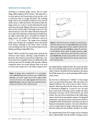
Figure 5. Geometrical-acoustic simulation of a performance hall with a primary source on stage (solid circles). a: IS method with a receiver (open circle). Asterisks, valid first-order ISs with their valid reflection paths (solid lines); crosses, ISs with their invalid reflection points outside the polygon geometry; open square, IS with a valid reflection point but with an obstructed path (dashed line). b: Ray-tracing method with a volumetric receiver (open circle). Reproduced from Savioja and Svensson, 2015, with permission.
Figure 4. Image source computation in a rectangular room (solid-line box) with a primary source (solid circle). Asterisks, first-order image sources (ISs); open circles, second-order ISs by circles; open squares, third-order ISs.,
dashed-line boxes, respective image rooms. Reproduced from Savioja and Svensson, 2015, with permission.
52 Acoustics Today • Winter 2020
