
Page 41 - Spring 2006
P. 41
The newsletter of
The Acoustical Society of America
THE OPTICAL MICROPHONE
Jürgen Peissig
Sennheiser Electronics GmbH & Co. KG Germany
Anew acoustical transduc-
er principle offers solu-
tions for special meas- urement applications. The most established microphone princi- ples—the dynamic microphone
and the condenser micro- phone—yield very good audio performance in a variety of applications from rugged stage operation to high fidelity audio recording in the studio. Yet
there are some situations where
these electro-acoustic transduc-
er principles lack in audio performance.
Optical transducer principles offer some specialties compared to other principles. The conversion of the acousti- cal signal is completed in two steps. First the sound is picked up by a membrane which transforms a constant source of light into an intensity-modulated light signal. The intensity modulation is proportional to the excursion of the mem- brane. In a photo detector such as a PIN diode (P-region, Intrinsic region, N-region) the light signal is then trans- formed into an electrical signal.
Advantages compared to other microphones—The microphone head can be placed distant to the light source and the photo detector. More than 300 feet of fiber-optical cable can be placed between those components without degrading the quality of the audio signal.
The optical microphone is completely insensitive to electrical and magnetic stray pick-up and thus gives the guarantee to measure only the acoustical signal at the posi- tion of the microphone head even in the presence of very strong electrical or magnetic disturbance (RF or static fields).
The optical microphone does not need electrical wiring to the microphone head. This eliminates possible interference with electromagnetic compatability (EMC)
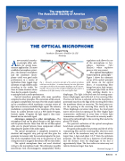
Fig. 1. Schematic construction principle of the optical microphone with lenses on the fibers. A constant intensity low noise light source emits light to the back of the microphone diaphragm via the transmit- ting fiber. The excursion of the microphone diaphragm then yields to a modulation of the light intensity in the receiving fiber (left).
regulations and allows the use of the microphone in haz- ardous locations (UL/ HazLoc) where explosive gases or dust are present.
The optical microphone: Construction principle— Figure 1 shows the schematic set-up of the optical principle with lenses on the optical fibers. A transmitting fiber brings low noise, high intensi- ty infrared light from an LED (light emitting diode) to a
diaphragm. This light is focused onto the moving mem- brane (diaphragm) and reflected to the receiving fiber. The focus of the lens is adjusted so that the focal point is positioned exactly on the edge of the receiving fiber when the membrane shows no excursion. The focal point cov- ers the opening of the receiving fiber exactly by half. When diaphragm excursion takes place, the focal point moves either onto the opening of the fiber (higher light transmission coefficient) or away from it (lower light transmission coefficient). This results in intensity modu- lation of the infrared light in the receiving fiber and at the photo PIN diode.
The practical realization of the optical microphone head shows several difficulties:
For good audio quality the position and the tilt of the transmitting fiber and the receiving fiber relative to each other and to the membrane may not show tolerances larger than 1-5μm and about 0.5-3° from the optimum positions. The fiber itself has a diameter of 200-230μm and the distance from the diaphragm to the lens is approximately 50μm. The lens radius curvature may not tolerate distances larger than 5μm.
Continued on page 41
Echoes 39
