
Page 43 - Spring 2006
P. 43
The Optical Microphone
Continued from page 39
Fig. 2. Transmitting optical fiber with lens (top) and receiving fiber without lens (bottom) fixed in the carrier frame (right). For better visibility the diaphragm was not mounted yet.
To yield these tolerances in a series production process the lenses are MEMS (micro-electro-mechanical- systems) manufactured and the fiber is placed in a micro- machined carrier frame which itself sits in a plastic hous- ing holding the membrane and the strain relief. Figure 2 shows the actual fiber glued onto the carrier frame. The membrane is placed on a membrane ring and is adjusted to the housing in a calibration process. This production process yields optimal performance of each individual microphone and is capable of compensating for other tol- erances in the microphone head.
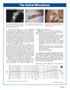
The transmission coefficient K changes with diaphragm excursion (distance to the fibers). It rises quite linearly toward a peak at a lens to fiber distance of 50 μm, and then decreases quite linearly. The microphone can operate either on the increasing (membrane is closer to the lens) or on the decreasing slope (membrane is further way from the lens) of the curve. The practical excursion of the membrane is only in the range of 500-1000 nm, thus yield- ing a good linear audio performance when the favorable working point is on the middle of the steepest slope.
Figure 3 shows a pre-production sample of the opti- cal microphone. The microphone has a diameter of 1/2 inch to be compatible with standard microphone meas- urement equipment. The frequency response of the
Fig. 4. Relative frequency response of the optical microphone.
Fig. 3. Pre-production sample of the optical micro- phone. The diameter of the microphone is 1/2 inch.
Fig. 5. Application of the optical microphone in the high-Tesla area of an MRI scanner for patient com- munication purposes.
microphone is shown in Fig. 4.
Applications—Since the optical microphone con-
tains no metal and no current or charges are flowing, it can be beneficial in the following situations:
• Operation under strong magnetic or electric or RF fields. The optical microphone guarantees, that the audio signal is absolutely free from any distur- bances that might be caused by those fields.
• Operation in hazardous locations. The optical microphone cannot generate ignition of explosive atmospheres or dust since it uses no electrical wires.
• Undetectable operation. Since the optical micro- phone does not contain metal, it cannot be detect- ed by metal detectors.
• Operation in high humidity.
As an example, Fig. 5 shows an application of the opti- cal microphone in an MRI scanner for patient communica- tion. The optical microphone does not disturb the imaging process since it contains no significant metal parts. The audio signal of the microphone is completely free from stray pick-up of the rapidly changing strong magnetic field com- ponents in the core zone of the MRI.
Jürgen Peissig is project manager for research projects at
Continued on page 42
Echoes 41
