
Page 22 - Summer 2006
P. 22
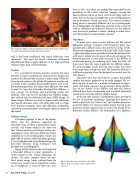
  Fig 5. Schroeder diffusers in the Michael Fowler Centre, New Zealand. (Photo cour- tesy of Dr. Harold Marshall of Marshall Day Acoustics)
 three in this case; these are grating lobes generated by the periodicity of the surface structure. Imagine viewing this polar response end on so that a set of three bright spots are seen; these are the type of images that x-ray crystallographers use to determine crystal structures. The acoustic problem being posed is somewhat different to x-ray crystallography. In crystallography, the diffraction patterns of the x-rays are used to determine an unknown structure. In the acoustic case, the inverse problem is solved—finding a surface struc- ture that produces a desired polar response.
Sequences
In many ways, room acoustic diffusers act like optical diffraction gratings. Consider a mid-frequency plane wave incident onto a diffuser such as the one shown in Fig. 4 (left). Plane wave propagation occurs within the wells. If the surface is rigid, then plane waves are reflected from the bottom of the wells and re-radiate into the space with no loss of energy. The scattered pressure at some point external to the diffuser is interference among the radiating waves from the wells. All these waves have the same magnitude but different phases. The phase changes results from the time it takes the sound wave to go down and up each well. The Schroeder diffuser is a diffraction grating where the designer has control over the wave phases.
Schroeder’s first step was to devise a surface that readily enabled the surface properties to be easily changed. His sec- ond step was to work out a method to determine an appro- priate well depth sequence that generated a phase distribu- tion on the surface of the diffuser and gave the desired reflected wave fronts. In inventing such a method, Schroeder turned to his favourite subject, number theory.
In the late 18th century, Carl Friedrich Gauss developed the law of quadratic reciprocity. Although best known to modern physicists for “Gauss’s Law” that explains properties of electric fields, it is Gauss’s number theory that led to the quadratic residue sequence that is used in the design of the quadratic residue diffuser. The formulation of a quadratic
 hall, it had been established that lateral reflections were
6
important . The need for lateral reflections influenced
Marshall and Hyde to apply diffusers to the large overhead surfaces rather than use flat reflectors.
Studios
It is a peculiarity of room acoustics research that most attention is paid to auditoria for classical music because the number of auditoria built each year is rather small. While dif- fusers found a place in the palette of treatments used in con- cert halls, it was actually in much smaller spaces, such as stu- dio monitoring rooms, that many more diffusers were used. Around the time that Schroeder developed his diffusers, a new concept for listening and monitoring rooms was explored. This was the live-end-dead-end (LEDE) design7, later refined into the reflection-free zone (RFZ) design. In these designs, diffusers are used to disperse early reflections that would otherwise arrive with little delay and at a high level. Without treatment, these early reflections (sometimes referred to as acoustic glare) would again color the timbre of the sound
Diffuser design
It became apparent to one of the authors (PDA) that the diffusers suggested by Schroeder were in-effect 2-dimensional “sonic crystals,” that scatter sound in the same way that 3-dimensional crystal lattices scatter elec- tromagnetic waves. Since the diffraction theory employed in x-ray crystallographic studies was applicable to acoustic reflection phase gratings, it was straightforward to model and design the Schroeder diffusers using techniques first developed in crystallography.
Figure 6 (left) illustrates the scattering from a Schroeder diffuser in polar coordinates. A source normal to the surface illuminates the surface. The polar response shows the one- third octave energy bands scattered from the surface as a receiver moves around the surface on a hemisphere. A series of lobes are seen,
   Fig 6. Scattered pressure level from a Schroeder diffuser (left) and a plane surface (right) of the same size.
 20 Acoustics Today, July 2006
