
Page 24 - Summer 2006
P. 24
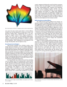
 Fig 8. Scattered pressure level from a modulated, optimized, reflection phase grating.
 to task a computer to laboriously search for the best sequences, but this is rather slow and inelegant. It is often much better to use those “unreasonably-useful” sequences that mathemati- cians have been producing for many centuries. The first sequence used for modulating diffusers was the maximum length sequence, also known as a Galois field. Maximum length sequences are based on mathematics developed by a 19th century mathematician Evariste Galois. Galois’s maxi- mum length sequences are used widely in digital systems. In acoustics they are probably best know for being an efficient signal for measuring linear time-invariant systems.
Reflection phase grating diffuser
The reflection phase grating diffusers have become ver- nacular in modern recording and broadcast studios. However, their appearance may be an impediment to their use in gener- al architectural spaces, especially given current tastes in archi- tecture and interior design. The diffuser’s appearance is not in keeping with modern architectural designs that now tend to use curves and more organic shapes. With Schroeder diffusers, the acoustic treatment is imposing a distinctive visual aesthet- ic. While there are architects who like form to follow function, most architects want to determine the visual aesthetic them- selves. If an architect thinks a diffuser looks ugly, it is unlikely to be used even if the treatment is vital to the acoustic design. Consequently, there is a need for designs that complement modern architectural trends.
Figure 10 shows a modern diffuser design on a concave wall. This is a curved diffuser designed to visually comple- ment the shape of the room, while providing the required acoustic performance. The diffuser disperses reflections from the concave wall that would otherwise lead to sound being focused in a particular spot. Figure 11 shows the polar response for the wall alone. It shows that the scat- tered energy level is much greater for the receiver at the focal point. In treating this focusing problem, it would have
 case across the most critical octave bands. A better diffuser would be one that distributed the energy more evenly in all directions without lobes. Consequently there is an issue. Using the original number theory design, periodicity is required, yet this results in non-optimal performance. Angus9, who showed that techniques developed for mobile telephony could be adopted for diffusers, devised a solution for this problem. These techniques are also applied to the design of loudspeaker and microphone arrays.
Spread spectrum techniques
Code division multiple access (CDMA) systems, using spread spectrum techniques, are used in mobile telephony to enable multiple users to use the same transmission bandwidth. Spread spectrum techniques take frequency (spectral) compo- nents and spread them over a frequency bandwidth. If the lobes generated by the Schroeder diffuser are viewed as spatial frequency components, the lobes will be spread spatially when spread spectrum techniques are used,. This is shown in Fig. 8, where the spread spectrum process has enabled the scattered energy to be redistributed from the three lobes shown in Fig. 6 to all directions (all spatial frequencies).
The most efficient way to achieve this spectrum spreading is to use a diffuser that is very asymmetrical, as shown in Fig. 9. The order of the diffusers is determined by chance with the diffuser placed in one orientation or opposite orientation. The diffuser array is no longer periodic and the periodicity lobes are suppressed. This produces a much more even polar response. While it is possible to use chance to determine the modulation sequence, it is better to use a properly-defined binary sequence. For a small number of diffusers, it is possible
    Fig 9. A cross-section through a modulated diffuser array based on an N=7 prim- itive root diffuser.
22 Acoustics Today, July 2006
Fig. 10. Optimized curved surface in the Edwina Palmer Hall, UK. (Photo courtesy of Arup Acoustics)
