
Page 26 - Fall 2006
P. 26
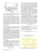
  Fig. 4. Wave speeds in a 10 cm thick steel plate; the longitudinal and shear waves are non-dispersive, and the bending waves are dispersive (speed varies with fre- quency). The thin plate wave speed becomes invalid at high frequencies where rotary inertia and shear resistance become important.
those in flimsy materials. Finally, structural waves are slower in massive materials than they are in lightweight materials.
In this tutorial, we have limited our discussions to homogenous, isotropic beams and plates. Many modern structures are constructed of combinations of materials that are far from homogenous and isotropic, like plates made of honeycomb cores and thin outer metal face sheets; or lami- nated composites, which are cured assemblies of layers of woven fibers and epoxies. These sorts of structures represent interesting challenges to structural-acousticians, and will be left to future articles.
Modes of vibration
We have learned generally about how waves propagate in structures. Now, we consider waves that reflect from struc- tural boundaries, and how they superpose with waves inci- dent on those boundaries.
Imagine operating a dial that controls frequency, and watching the left and right traveling waves in a finite structure
10
traveling waves that move at finite speeds.
Modes of beams
We will consider first the simplest flexural resonances— those in a simply supported straight beam of length a. The resonance condition is found from the simply supported boundary conditions, where there is no motion, and no moment resistance by the supports.
The frequencies of resonance for Bernoulli-Euler (thin) beams are found by combining the wave speed equation with the resonance conditions, leading to
which correspond to the mode shapes wm(x) = sin(mπx/a), for 0 < x < a. There are an infinite number of modes as m increases from 1 to infinity. Note that the resonance frequen- cy is the product of the square of the modal wavenumber11 (km = mπ/a) and the square root of the beam parameters EI/ρA. We will see that for other boundary conditions, the resonance frequencies still depend on EI/ρA, but will change as the wavenumber of the mode shape changes.
The mode shapes for m=1 through 4 are shown in Fig. 5 for a simply supported straight beam. In the mode shapes, dashed lines indicate the locations of maximum amplitude (the anti-nodes). The nodes of the mode shapes are at points of near zero vibration. A useful way of determining the orders of mode shapes measured on structures with nearly simply supported boundary conditions is to count the num- ber of antinodes (try it in the figures).
I often refer to the modes of simply supported structures as the analyst’s best friend, since they are easy to incorporate into advanced theories of sound radiation, and into analyses of the flow turbulence acting on structures. It is hard to find something much simpler than a sine wave to integrate!
Unfortunately for the analysts, modes in structures with free (and other) boundary conditions are more complicated than those in ideal simply supported structures, since the free edges impart a near field deformation to the vibration and shapes. For example, for a free beam of length a, the resonance frequencies may be computed only approximately, where
(17)
For m=2 and 3, the above formula may still be used, but can be in error by greater than 20-30%.
There are no simple formulas for the mode shapes of free beams, but we can refer to Leissa’s compendium of plate mode shapes12 to infer the following:
  As the wavelengths shorten with increasing frequency, they pass through specific frequencies where left and right traveling waves either destructively inter- fere (anti-resonance), or constructively interfere (resonance). The constructive interference in resonance causes the appear- ance of ‘standing waves’ with high vibration amplitudes, where it does not appear that the waves are traveling at all, but that there is a stationary wave that oscillates in place. Remember that in reality, the standing wave is comprised of left and right
shorten as the dial is turned.
(18)
and
    24 Acoustics Today, October 2006
, (16)
Fig. 5. The first four mode shapes of a simply supported beam. The dashed lines indicate the vibration antinodes, or locations of maximum deformation.
