
Page 23 - Spring 2007
P. 23
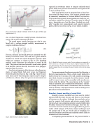
  Fig. 14. Sound power radiated by Schedule 10 Steel 3 inch pipe with elbow, pipe length/diameter~12.
(27)
required in reverberant rooms to compute radiated sound power, many more pressure measurements are required to do so in an anechoic room.
Total sound power must be integrated over a closed sur- face around the sound source. Also, acoustic intensity must be measured, sometimes in the near-field of the structure. This means many intensity measurements are made over sev- eral points around the structure. The points may be defined over a hemisphere or a box-like shape. Standards are avail- able18 to guide your measurements, and acoustic intensity probes, like the one shown in Fig. 16, are widely available.
 cies. At other frequencies, usually between structural reso- nances, the structure attenuates the drive.
The sound power transfer functions can also be com- bined with a surface-averaged mobility measurement to compute radiation efficiency:
.
Pressure, intensity, and sound power are measured very dif- ferently in anechoic rooms. The walls of a typical anechoic chamber are coated with sound absorption materials. Foam wedges are common, as shown in Fig. 15. The absorbing material nearly eliminates the reflection of sound by the walls. The pressure measured around a sound source placed in an anechoic room is due only to acoustic waves propagat- ing away from the source.
Anechoic environments allow for more refined measure- ments of sound fields, both over space and frequency. Directivity plots like those in Fig. 3 and Fig. 8 may be meas- ured. Also, narrow-band frequency spectra may be comput- ed. However, whereas only a few pressure measurements are
 Fig. 16. Hand-held acoustic intensity probe. Two microphones are separated by a known distance Δx so that particle velocity may be computed using a finite differ- ence approximation. The mean pressure and estimated particle velocity are com- bined to compute the active, or real part of acoustic intensity in the direction along the x-axis.
Two measurement chambers are required to determine a barrier’s transmission loss. Often, a thick, nearly rigid wall is built between the two rooms. The wall includes an opening, into which a barrier is mounted. One of the rooms is consid- ered the ‘source’ room, and is ensonified with sound waves, which strike the barrier. The sound power in the ‘receiver’ room is measured, and a transmission coefficient is calculat- ed. Usually, the source room is reverberant, and the receiver room is anechoic, with measurements made according to the procedures we described above.
Boundary element modeling of sound fields
Boundary element methods have been used to predict acoustic fields for about 45 years, and there is a vast amount of literature on the subject. Although these methods can be used to compute both interior and exterior acoustic fields, the focus here is on computing exterior acoustic fields where boundary elements have distinct advantages. Since this arti- cle is at the level of a tutorial, our main goal will be to give the reader a brief synopsis of the basic analysis techniques and the current state of the art. For the sake of simplicity, the specified boundary condition and radiated acoustic field are assumed to be time-harmonic.
A completely general solution for the pressure field of a
  Fig. 15. ARL/Penn State's Anechoic Chamber.
Structural Acoustics Tutorial 2 21
