
Page 30 - Winter 2008
P. 30
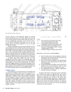
  Fig. 5. Floor plan with music delay zones.
 the best solution. If the loudspeaker heights are uniform and the loudspeaker type is the same, delays are increased as the listener position moves farther from the source. In this way, loudspeakers covering an area in front of a listen- er can provide additional directional cues to the area behind. This is an excellent approach in the case of large reverberant churches.
Another consideration in sound system design is that the source origination point, whether speech or music, may vary depending on the source position. For example a talker locat- ed at an altar will provide a different source origination point than a choir. Using individually amplified distributed loud- speakers, different delays can be employed that depend on the source origination point. In this way even coverage can be maintained while the perceived source direction is changed.
At Mount Saint Mary’s Chapel the room was small enough that the talker could be the localizing source. For each talker location, the delays were set for each distributed speaker. Figure 5 shows a typical configuration. The design is much like dropping a pebble in a pond and watching the waves move outward from the origination point. By locating micro- phone plug boxes in the floor near the originating point, each box would uniquely define the associated delay pattern.
Feedback control
In the design of every sound system we must address the phenomenon of feedback. Figure 6 shows the geometry of a simple sound system having a talker, a microphone, and a loudspeaker. Feedback occurs when the direct sound level from a loudspeaker exceeds the sound level from the talker at the output of the microphone. Under these conditions a feed- back loop is created which produces a howl in the system. To avoid this condition, the talker level must exceed the loud- speaker level by a certain margin of safety called the feedback margin of stability
(6)
  28 Acoustics Today, January 2008
From this we see the ways to control feedback:
1) Move the talker closer to the microphone so that the system gain can be reduced and thus the level at the microphone from the loudspeaker;
2) Select a directional microphone that preferentially emphasizes sounds coming from the talker, relative to the loudspeaker;
3) Design loudspeakers that deliver more sound to the listeners than to the microphones, either by using directional loudspeakers or a distributed system;
4) Use equalization, frequency shifting, compression, and other electronic techniques.
At Mount Saint Mary’s Chapel all of these techniques were utilized. The system was equalized for music with a house curve which rolled off 4 dB per octave above 3k Hz. Additional equalization was included in the speech path, tuned to the major feedback frequencies. Cardioid micro- phones were used at the fixed talker positions. Earset micro- phones were used for the wireless transmitters. A frequency shift of 10 cents (1200 cents/octave) was also electronically introduced as a safety measure.
