
Page 13 - Summer 2008
P. 13
assume that the flaws can be characterized by acoustic point scatterers in the near-field. Therefore, spherical wave fronts impinge on our measurement array emanating from these flaws. The SAFT approach creates an image by assuming that the flaw location is at the given pixel, calculates the associat- ed propagation delays and attenuations assuming a homoge- neous medium, beamforms the measured data based on these assumptions and estimates the power in the beam at the assumed location (pixel or point scatterer). This procedure is repeated for each pixel until the observed power image is formed. Of course, this methodology can also be applied to image the results of time-reversal focusing and decomposi-
15
based on replacing the beamformer with a propagation model. The same scheme (as above) applies, but the propagation model generates (backpropagation) the equivalent signal at the array and a criterion is created to “decide” whether a flaw is at a given
7
test location (pixel or point scatterer). The propagation model
can be as sophisticated as deemed necessary incorporating fea-
tures such as both compressional and shear waves, multipath,
dispersion, and noise. This model-based technique is called
matched-field imaging (MFI) and enables the acoustician to use
the a priori information available in a formal procedure to cre-
16,17
7
positionofaflaw(ortarget). Notethatinthefiguretheplotsare
actual laser ultrasound array measurements. The object is a hole
(flaw) drilled into an aluminum plate and measured using a syn-
14
tion of the operator for localization purposes.
Another more acoustics-oriented approach for imaging is
MFI is illustrated in Fig. 5 where we observe the measurements and propagation model generating the com- ponents of a decision function used to “detect” or “localize” the
ate the image.
thetic aperture technique created for processing and detection.
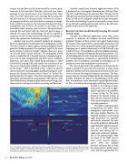
Consider a typical laser ultrasonic application where a NDE is performed on a rectangular aluminum part with two flaws. The SAFT and MFI images are shown in Fig. 6. We note that the MFI approach incorporates both compressional and shear wave fronts as well as the multipath caused by the part boundaries. The results of estimating the power at each pixel is shown where we see the high resolution and accurate results of the MFI com- pared to those of the SAFT processor.
Recursive (in-time) model-based processing for a towed acoustic array
Consider the following application taken from ocean acoustics to motivate the modern recursive model-based approach. Suppose we have a plane wave signal characterizing an acoustic source measured by a horizontally towed array. The plane wave is at a 50 Hz temporal frequency and a bearing of 45o impinging on a 2-element towed array at a 10 dB SNR with a tow speed of 5 m/sec. We would like to solve the problem of extract- ing the source bearing and temporal frequency parameters—the critical information we seek. From the model-based perspective, the bearing/frequency estimation or equivalently, localization problem can be considered a problem of estimating a set of
18,19
parameters from noisy hydrophone measurements.
The classical approach to this problem is to assume that the signal is separable in space and time and select a single sensor channel to perform spectral analysis/peak detection on the time series to estimate the temporal frequency parameter. The bear- ing can then be estimated independently by performing spatial spectral estimation (as before) or beamforming on the array data. A beamformer can be considered a spatial spectral estima- tor that is scanned over bearing angles indicating the true source location at the bearing of maxi- mum power. The result of apply- ing this approach to our problem is shown in Fig. 7a. The figure illustrates the classical outputs of both spectral estimators peaking at the correct frequency and bear-
ing angle parameters.
The MBP is implemented by
incorporating the plane wave propagation, hydrophone array, and noise models. However, the temporal frequency and bearing angle parameters are unknown and must be estimated. The solu- tion to this problem is obtained by augmenting the unknown param- eters into a MBP state-space structure and solving the so-
7
This is the parametrically adap-
tive form of the MBP used in
most ocean acoustic applica-
18
called joint estimation problem.
Here the problem becomes nonlinear due to both the measurement model (plane wave) and the augmentation. It is
tions.
Fig. 6. Acoustical imaging of laser ultrasound flaw detection for NDE of aluminum part: (a) SAFT imaging; (b) model-based matched-field imaging; (c) thresholded SAFT image for flaw localization \[(12.03 mm, 2.79 mm),(9.89 mm, 5.02 mm)\]; (d) thresholded model-based matched-field image for flaw localization \[(11.99 mm, 2.94 mm), (9.98 mm, 5.03 mm)\].
12 Acoustics Today, July 2008
