
Page 17 - Winter 2009
P. 17
DESIGNING AND BUILDING
A LOW-NOISE HEMI-ANECHOIC CHAMBER
Douglas F. Winker
ETS-Lindgren Cedar Park, Texas 78613
“The chamber exceeded the specification with a noise floor that was > 0 dBA for frequencies ≥100 Hz and only 5 dBA at 80 Hz.”
Noise emission and noise control air conditioning (HVAC) system must
are common topics in the field
of acoustics. Noise emission
from devices needs to be measured to
comply with noise standards and to
develop quieter devices. To make these
measurements, a quiet noise-controlled
environment is required. A large con-
vertible hemi-anechoic chamber was
constructed at ETS-Lindgren’s head-
quarters in Cedar Park, Texas for that
purpose. The project was a noise control project unto itself with the goal to measure the noise produced by a wide vari- ety of test specimens.
ETS-Lindgren Acoustic Systems operated a laboratory in south Austin, Texas beginning in 1985. The south Austin lab- oratory had a suite of reverberation chambers and a hemi- anechoic chamber with a 1-meter, precision-grade free field above 125 Hz. Over the years, tested product noise became lower and lower, especially for information technology (IT) equipment. As product noise emissions decreased, their acoustic performance began to encroach on the chamber’s noise floor and the quietest of products were tested late at night when the ambient levels were at their lowest (approxi- mately 17 dBA). Highway expansion was the main contribu- tor to the noise floor increase. The laboratory was located less than 2 miles away from the Interstate 35 and US Highway 290 interchange. When the chamber was constructed, this inter- change did not exist and was not part of the design parame- ters. After the construction of this interchange, low-frequen- cy traffic noise became measurable inside the chamber.
In 2006, the decision was made to move the ETS- Lindgren Acoustic Systems’ laboratory and production facil- ities to ETS-Lindgren’s headquarters in Cedar Park, Texas. The team decided to decommission the old chambers and build an entirely new lab with a double-wall hemi-anechoic chamber (i.e., a chamber within a chamber) that had a larger free field and a much lower noise floor. Low-noise testing had to be possible at all times of the day regardless of the noise sources outside the chamber.
The chamber’s design was dictated by the project’s goal— a mandate to test a wide variety of devices. First, the ability to test low-noise products was required and a noise floor of NC- 10 at any microphone on the measurement surface was spec- ified. Additionally, low-noise testing had to be possible at any time regardless of the activities outside the chamber includ- ing future highway expansion. Second, a 2-meter radius pre- cision-grade (ISO 3745:2003) hemispherical free field was required for frequencies ≥80 Hz. Third, using a paral- lelepiped array, two full height equipment racks must be able to be tested side by side. Fourth, the heating, ventilating, and
not affect the chamber’s noise floor and must maintain controlled temperature levels of ± 2° C with a high heat load. An addition to the HVAC requirement was that the lighting system should not con- tribute additional heat to the chamber and the system must be low noise. The fifth design requirement has not been fully implemented—the chamber must be able to be converted into a fully ane-
choic chamber. As part of this requirement, the chamber’s wedge basket doors were designed to accommodate remov- able floor wedge carts, but these carts have not been con- structed.
The inner chamber rests on an isolated concrete slab that was designed with the future in mind. The chamber’s loca- tion in Cedar Park, Texas is approximately 40 km from downtown Austin and there is considerably less traffic in the area. While the area is somewhat remote now, continuing expansion will eventually engulf the area. With this expan- sion comes increased traffic and road noise. Highway expan- sion is underway and a light rail system will go online in the spring of 2010. The isolation system was designed with this growth in mind.
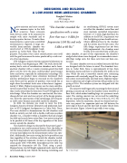
The concrete work began with excavating the host site and pouring a concrete pit so that the chamber’s entry would be at floor level, which makes handling large test specimens much easier. The existing concrete was cut out and the underlying soil was excavated leaving a 7.92 x 7.92 x 0.56 m (L x W x H) depression. After the excavation, the pit was framed and con- crete was poured. An expansion joint was left between the outer edge of the pit and the host slab to isolate the pit from host site noise. Figure 1 shows the pit while it was curing.
Fig. 1. Concrete pit.
16 Acoustics Today, October 2009
