
Page 18 - Winter 2009
P. 18
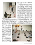
  Fig. 2. Spring isolators during installation.
Once the pit was poured, the isolated concrete slab could be framed and poured. The floating slab resides entirely in the pit and is supported by 54 spring isolators (Fig. 2). The spring isolators were placed in the pit and strapped together with reinforcing bar. Next, 45.46 metric tons of concrete were poured resulting in a 30.5 cm thick concrete slab with a foot- print of 6.1 by 6.1 m. The floating slab acts as the chamber’s reflecting plane. The slab also features
a 30.5 by 30.5 by 10.2 cm (L x W x H)
recess at its center to hold floor-
mounted sound sources or to flush-
mount a motorized turntable capable
of rotating test specimens up to 225 kg.
A 1.25 cm thick steel plate covers the
opening when the turntable or sound
source is not in use. A 30 cm wide
cable recess allows cables to run into
the pit without disturbing the reflect-
ing plane. A series of 1.25 cm thick
steel plates cover this recess. Several
holes were bored into the slab and act
as mounting points for the various
microphone arrays used during test-
ing. Finally, an epoxy finish was
installed to create a smooth and
durable finish.
The inner chamber was construct- ed on the isolated concrete slab and raised into position after construction. This was a tedious process that involved gradually raising each spring isolator in succession by a small amount and repeating the process until the isolated slab was flush with the host slab. This
process can be seen in Fig. 3. Upon the completion of this operation, the bottom of the isolated slab was 7.62 cm above the floor of the pit.
The inner and outer chambers were constructed simulta- neously after the concrete work was complete. The outer chamber walls are 10.16 cm thick and rest on the edge of the concrete pit. An 11-gauge steel perimeter channel was installed around the edge of the pit to receive the modular wall panels. A closed-cell foam gasket was installed beneath the perimeter channel to fill any voids that might exist between them and the concrete surface. Each of the wall pan- els was constructed in ETS-Lindgren’s factory and transport- ed to the job site. These panels were constructed to achieve high noise reduction. The outer surface of each panel is 16- gauge cold-rolled steel. Inside the panel, a 2.54 cm thick layer of gypsum board was laminated to the outer skin to increase the outer surface’s overall mass. The remaining cavity was filled with cotton fiber fill that is 7.62 cm thick. The inner surface is another layer of 16-gauge cold-rolled steel. The assembly is held together by 16-gauge cold-rolled steel chan- nels, which are welded in place. The wall panels fit into a labyrinth joiner system constructed using 11-gauge cold- rolled steel. Every joint and seam was filled with a bead of latex caulk. All of the steel in the chamber was powder coat- ed for a lasting rust-free finish. The external dimensions of the outer chamber are 8.69 by 8.69 by 7.32 m (L x W x H) above the finished floor. Figure 4 shows an outer chamber wall installed in one of the perimeter channels.
The inner chamber walls are 30.5 cm thick and rest entirely in another 11-gauge steel perimeter channel that is attached to the isolated concrete slab. They are separated from the outer chamber walls by 30.5 cm. This space is filled
  Fig. 3. Raising the inner chamber.
Low-Noise Hemi-Anechoic Chamber 17
