
Page 20 - Winter 2009
P. 20
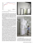
  Fig. 7. ASTM E1050 normal incidence sound absorption test results for a 30.5 cm panel with and without wedges installed.
  Fig. 8. Completed chamber with double doors open.
resulting total depth of treatment is 0.86 m. Figure 7 shows the results of an ASTM E1050 (Standard Test Method for Impedance and Absorption of Acoustical Materials Using A Tube, Two Microphones and A Digital Frequency Analysis System) normal incidence sound absorption test of the 30.5 cm panel by itself and with the wedges installed. The tests were performed in a 61 cm by 61 cm square cross section impedance tube.
Large test specimens are loaded into the chamber though two sets of double doors. The first set of doors is mounted in the outer chamber wall and has a 2.74 by 3.05 m clear opening. The second set of doors is mounted in the inner chamber wall and has a 2.44 by 2.74 m clear opening. Each door has its own automatic door opener. The automatic door openers are syn- chronized to open or close each door leaf in a specific order with the push of a single button. Figure 8 shows the completed chamber with the double door open. Inside the chamber two wedge doors cover the opening. Each wedge door measures 3.05 by 1.83 m (H x W) and moves out and sideways on a two- pivot hinge system and are shown in Fig. 9.
One of the challenges with such a low noise floor was the need for silent environmental control. The chamber’s internal volume is 200 m3 and has an air change every 6 minutes. To accommodate the required air flow rate and eliminate any duct-borne noise, a series of HVAC silencers were installed. Only one inlet path and one outlet path were used on the chamber with two HVAC silencers installed in each path. The first silencer, in the inlet path, is housed in a 10.16 cm thick panelized housing. The outer layer of the housing is 16-gauge steel with a 2.54 cm thick layer of gyp- sum board laminated to its inner surface. Next, 7.62 cm of fiberglass-free sound absorbing material was added and then the inner skin, a second layer of 16-gauge steel, was applied. Inside this housing, a 3.05 m long, high-perform- ance splitter-type silencer with a 0.61 by 0.61 m cross sec- tion was installed. This housing was suspended from the host building’s ceiling with vibration isolation mounts to decouple any vibrations that might be transmitted from the building or the HVAC system even though it was attached to the HVAC system with flexible duct work. The outer HVAC silencer housing passes through the chamber’s ceil- ing through an isolated collar, which physically separates it
  Fig. 9. One wedge basket door in operation.
 from the chamber’s structure.
A second HVAC silencer for the inlet path was installed
between the outer and inner shells of the chamber. Due to its location between the chamber walls, a separate housing was not constructed around this silencer. The inner silencer is
Low-Noise Hemi-Anechoic Chamber 19
