
Page 21 - Winter 2009
P. 21
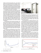
  Fig. 10. Control room.
similar in construction except that it has a cross section of 0.30 by 0.91 m. The end of this silencer terminates with a 90 degree turn through the top of the inner chamber. Acoustic turning vanes are in all 90 degree turns within the HVAC sys- tem to maintain laminar flow and provide sound attenuation. No vent grilles were used at the opening inside the chamber in order to eliminate flow-generated noise. The inlet and out- let path silencer solutions are identical except for the orienta- tion of the silencers due to the air flow direction.
Two different sets of lights were installed in the cham- ber. Each style of light met the design requirements of not introducing heat into the chamber and not contributing to the noise floor. Normally, only one style of light is installed but both types were installed for demonstration purposes. The first style of light uses a standard can-type housing with a light emitting diode (LED) bulb system. The second light- ing system is a fiber optic system. The system consists of two 150-watt metal halide bulbs that are mounted outside of the chamber. Light is delivered by eight fiber optic bun- dles that pass through the ceiling of both the inner and outer chambers and terminate inside the chamber. All of the fiber optic bundle penetrations were treated to eliminate flanking paths.
To accommodate a wide variety of test specimens, a col- lection of electrical outlets was installed on the chamber. The electrical outlets range from 110 Vac single phase to 480 Vac three phase service. Both 50 Hz and 60 Hz service is avail- able. The electrical panel is located on the outside of the outer chamber and the required electrical lines are passed through an acoustically treated penetration in the chamber walls. The reason for mounting the electrical panel outside of the cham- ber was to minimize the number of penetrations through the chamber walls.
To maintain client confidentiality and secure client test devices, a control room was constructed adjacent to the chamber. The control room consists of three walls and a ceil- ing, which was constructed using 10.1 cm thick panels. These panels are the same type of panel as used in the outer cham- ber walls. The fourth wall of control room is a section of the outer chamber’s wall, which contains a personnel access door into the chamber. Instead of attaching the control room walls and ceiling to the outer chamber walls, the control room is separated from the outer chamber wall by 1 cm and the ceil- ing along this wall is supported by columns that attach to the
Fig. 11. Ambient sound pressure levels.
host slab and not to the isolated pit. The gap between the walls was filled with a high-density neoprene foam gasket. The con- trol room measures 8.69 by 3.66 by 3.05 m (L x W x H). This room is fed by a separate HVAC and silencer system to elimi- nate the possibility of noise flanking into the chamber from the control room through the HVAC system. The control room is shown in Fig. 10.
Once construction was completed, performance verifi- cation testing began. The first test conducted was to measure the chamber’s noise floor to confirm that it met the specifica- tion of a level not exceeding NC-10 at any of the microphone positions on the measurement hemisphere. The chamber was tested at each location using a GRAS Type 40 HH low-noise microphone. The chamber exceeded the specification with a noise floor that was > 0 dBA for frequencies ≥100 Hz and only 5 dBA at 80 Hz. The noise floor is shown in Fig. 11. The noise floor is verified regularly as part of the laboratory’s accreditation program and has not increased even though substantial highway construction has been completed and traffic has increased in the area. Also, several construction projects are ongoing in the area and none of them has affect- ed the noise floor in the chamber.
The next test program was to verify the chamber’s free- field performance. Using ETS-Lindgren’s automated traversing rig, several sets of traverse or draw away data were taken in accordance with ISO 3745:2003 (Acoustics—Determination of sound power levels of noise sources using sound pressure— Precision methods for anechoic and hemi-anechoic rooms). The chamber was found to have an ISO 3745:2003 compliant
  Fig. 12. Deviations from inverse square law at 100 Hz and 80 Hz.
  20 Acoustics Today, October 2009
