
Page 18 - Acoustics Today
P. 18
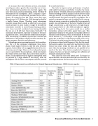
                                As in many other data collection systems, autonomous recordings are only as good as the sensors they use to trans- duce environmental quantities into electrical signals. The noise floor of an acoustical monitoring system will likely be determined by the microphone. Table 1 compares a repre- sentative selection of commercially available electret micro- phones, all costing less than $20. These sensors have noise floors that are 14-37 dB above the 1 kHz hearing threshold of a healthy human listener. Therefore, many autonomous recorders cannot detect sounds as effectively as an experi- enced naturalist. In some studies, it might be desirable for autonomous recorders to exceed human hearing perform- ance. Some terrestrial vertebrates have hearing thresholds
7-9
quency response, directivity, and robustness.
Microphone power consumption merits brief considera-
tion. For a 30 day continuous deployment, these micro- phones would require between 12 and 432 mAh of battery capacity, which is likely to be a negligible fraction of the over- all system power budget. However, if an independent power source is provided for the microphones, which may improve the overall system noise floor, then current drain may be a factor. The microphone with the highest consumption could be powered by a single alkaline 9 volt battery, while the microphone with the lowest consumption could be powered
by a small coin battery.
One tactic to improve system performance is to physi-
cally amplify incoming sound before it reaches the micro-
11
To understand their behavior, especially in relation to the mask- ing effects of noise,10 instruments are needed that can outper- form their hearing. In addition to noise floor, selection and deployment of microphones should consider sensitivity, fre-
that are up to 20 dB lower than human thresholds.
Parabolic reflectors are widely used to make focused recordings of vocal animals, but these devices realize their gain inside a very small solid angle, so they do not sub- stantially expand the spatial coverage of a microphone. For a conical or exponential horn, gain is realized by the concen- tration of energy as sounds are confined by the progressively smaller cross sectional area of the horn. Consider a horn of length L, mouth area Sm and throat area St. At high frequen- cies, the gain relative to a free field microphone is approxi- mated by 10log10(Sm/St). For a given mouth size, a smaller microphone element will realize greater horn gain. This approximate formula for the gain of a horn applies above the specified cutoff frequency, which is determined by the flare rate of the horn. Fc = ca/(4π),where c is the speed of sound in meters per second and a is the flare rate, equal to ln(Sm/St)/L. This formula is easily inverted to calculate the flare rate need- ed to insure a desired cutoff frequency. Note that this simpli- fied analysis neglects the constructive and destructive inter- ference that occurs within the horn and other effects that arise when the incoming wavefronts are not parallel to the mouth of the horn. These factors complicate the frequency response function and present challenges for calibration of
phone element.
measured sound pressure levels.
What limits the size of the mouth area? The larger the
mouth becomes, the more directional the sensor becomes. To a first approximation, the directivity of the horn microphone
 Table 1. Representative specifications for Original Equipment Manufacturer (OEM) electret capsules
 1V/Pa
Bioacoustical Monitoring in Terrestrial Environments 17
