
Page 13 - Winter2014
P. 13
beam-formers and Decoherence
Before getting to details of how the decorrelation/decoherence of a signal causes loss of array signal gain, it would be good to quickly review how basic array beam-formers work. There are two types
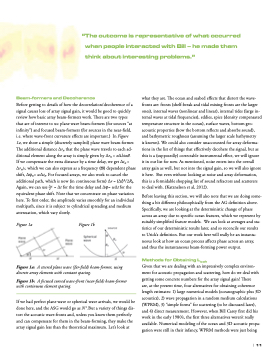
that are of interest to us: plane wave beam-formers (for sources “at infinity”) and focused beam-formers (for sources in the near-field, i.e. where wave-front curvature effects are important.) In Figure
1a, we show a simple (discretely sampled) plane wave beam-former. The additional distance ∆rn that the plane wave travels to each ad- ditional element along the array is simply given by ∆rn = n∆lsin0.
If we compensate the extra distance by a time delay, we get ∆tn = ∆rn/c, which we can also express as a frequency (π) dependent phase shift, ∆φn= w∆tn. For focused arrays, we also work to cancel the additional path, which is now (in continuous form) ∆r = (∆l)2/2R0. Again, we can use ∆r = ∆t for the time delay and ∆φ= w∆t for the
equivalent phase shift. Note that we concentrate on phase variation here. To first order, the amplitude varies smoothly for an individual multipath, since it is subject to cylindrical spreading and medium attenuation, which vary slowly.
what they are. The ocean and seabed effects that distort the wave- fronts are: fronts (shelf-break and tidal mixing fronts are the larger ones), internal waves (nonlinear and linear), internal tides (large in- ternal waves at tidal frequencies), eddies, spice (density compensated temperature structure in the ocean), surface waves, bottom geo- acoustic properties (how the bottom reflects and absorbs sound), and bathymetric roughness (assuming the larger scale bathymetry
is known). We could also consider unaccounted for array deforma- tions in the list of things that effectively decohere the signal, but as this is a (supposedly) correctable instrumental effect, we will ignore it in our list for now. As mentioned, noise enters into the overall array gain as well, but not into the signal gain, so we will also ignore it here. But even without looking at noise and array deformation, this is a formidable shopping list of sound refractors and scatterers to deal with. (Katznelson et al, 2012).
Before leaving this section, we will also note that we are doing some- thing a bit different philosophically from the AG definition above. Specifically, we are looking at the deterministic change of phase across an array due to specific ocean features, which we represent by suitably simplified feature models. We can look at averages and sta- tistics of our deterministic results later, and so reconcile our results to Urick’s definition. But our work here will really be an instanta- neous look at how an ocean process affects phase across an array, and thus the instantaneous beam-forming power output.
Methods for Obtaining Lcoh
Given that we are dealing with an impressively complex environ- ment for acoustic propagation and scattering, how do we deal with getting some concrete numbers for the array signal gain? There
are, at the present time, four alternatives for obtaining coherence length estimates: 1) large numerical models (oceanographic plus 3D acoustics), 2) wave propagation in a random medium calculations (WPRM), 3) “simple forms” for scattering (to be discussed later), and 4) direct measurement. However, when Bill Carey first did his work in the early 1980’s, the first three alternatives weren’t really available. Numerical modeling of the ocean and 3D acoustic propa- gation were still in their infancy, WPRM methods were just being
Figure 1a
Figure 1b
c
“The outcome is representative of what occurred when people interacted with bill – he made them think about interesting problems.”
Figure 1a: A steered plane wave (far-field) beam-former, using discrete array elements with constant spacing.
Figure 1b: A focused curved wave-front (near-field) beam-former with continuous element spacing.
If we had perfect plane wave or spherical wave arrivals, we would be done here, and the ASG would go as N 2 .But a variety of things dis- tort the acoustic wave-fronts and, unless you know them perfectly and can compensate for them in the beam-forming, they make the array signal gain less than the theoretical maximum. Let’s look at
| 11
