
Page 19 - Summer 2015
P. 19
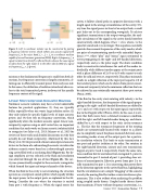
 Figure 3. Left: A nonlinear isolator can be constructed by pairing a frequency-selective mirror, which reflects any acoustic signal with frequency f0 in the reject band, f1 < f0 < f2 to a nonlinear medium capable of second-harmonic generation (SHG). Right: At frequency f0 , a signal incident from the left is reflected (red), whereas the same signal incident from the right makes it to the other side by SHG of a signal at frequency fSHG > f2 (green).
mission at the fundamental frequency is small from both di- rections, but frequency conversion is largely asymmetric, al- lowing one to efficiently transmit power from only one side. In this sense, the definition of isolation introduced above re- fers to the total transmitted power, irrelevant of the specific frequency content of the signal.
Linear Nonreciprocal Acoustic Devices
Nonlinear acoustic isolators may have several undesirable features for practical applications: (1) they are typically bulky, especially when one wants large isolation ratios; (2) they only isolate for specific (high) levels of input acoustic power; and (3) they rely on frequency conversion, which significantly alters the incident acoustic signal. Linear non- reciprocity requires using an odd-vector bias, an important condition that early works on linear acoustic isolation failed to recognize (see Jalas et al., 2013; Maznev et al., 2013 for reviews of these works and detailed discussions on why they actually do not break reciprocity). Motivated by this fact, Fleury et al. (2014) presented a linear nonreciprocal acoustic device in the form of a subwavelength acoustic circulator for airborne acoustic waves based on a subwavelength acoustic ring cavity filled with a circulating fluid (Figure 4a). For de- sign simplicity, air was selected as the fluid and circulation was achieved through the use of fans (Figure 4b). The cav- ity was symmetrically coupled to three acoustic waveguides, which formed the input and output channels of the device.
When the fluid in the cavity is not circulating, the structure operates as a reciprocal sound splitter, which equally divides the input power to the output ports as explained in the fol- lowing. Consider the case where the structure is excited from port 1 with frequency ω. When the signal enters the
cavity, it follows closed paths in opposite directions with a length equal to the average circumference of the cavity l. Ev- ery time the signal passes in front of an output hole, a small part leaks out to the corresponding waveguide. To achieve significant transmission at the output waveguides, the mul- tiple circulations of the signal in the cavity should interfere constructively, which happens if lω/c = 2mл, where c is the speed of sound and m is an integer. This equation essentially provides the resonant frequencies of the cavity modes, which are pairs of counterrotating modes with azimuthal depen- dence е±imφ, where “plus” and “minus” signs correspond to waves propagating in the right- and left-handed directions, respectively, and φ is the polar angle. The above condition leads to constructive interference for each of the modes in- dividually, while different modes appear at the output ports with a phase difference of 2л/3 or 4л/3 with respect to each other for odd and even m, respectively. This phase mismatch results in a slight reflection at the input port equal to 1/9 of the incident power, which can be shown from power conser- vation and reciprocity to be the minimum reflection that can be achieved in any rotationally symmetric three-port system (Pozar, 2005).
If the fluid in the cavity starts rotating with velocity v in the right-handed direction, the frequencies of the signals propa- gating in the right- and left-handed directions are shifted by -ωv/c and ωv/c with respect to the input signal, respectively, due to the Doppler effect (Pierce, 1981). In this case, it is evi- dent that both waves have a detuned resonance condition, with the right- and left-handed modes being up- and down- shifted by ω0v/c with respect to the static cavity resonance ω0 . The fact that the resonance frequencies of the rotating modes are symmetrically located with respect to ω0 allows one to completely cancel the phase mismatch between coun- terrotating modes at one of the output ports for a particu- lar circulation velocity. This leads to unity transmission at one port and perfect isolation at the other. For rotation in the right-handed direction, unitary and zero transmission happen at ports 3 and 2, respectively. Under the same rota- tion condition but for excitation from waveguide 3, power is transmitted to port 2 instead of port 1, providing clear evi- dence of nonreciprocity. Likewise, power from port 2 is to- tally transmitted to port 1. It is interesting that power flows in the direction opposite to the cavity fluid bias, highlighting that the circulation is not a simple “dragging” of the acoustic wave by the moving fluid but rather a wave interference phe- nomenon. This is also evident when analyzing the problem using coupled mode theory. Coupled mode theory shows that maximum IS (now without frequency conversion), i.e.,
 Summer 2015 | Acoustics Today | 17
