
Page 20 - Summer 2015
P. 20
Nonreciprocal Acoustics
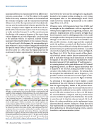
maximum difference in transmission between different out- put ports, occurs when v = c/(2Q√3), where Q is the quality factor of the cavity resonance, defined as the ratio between the resonance frequency and the transmission bandwidth (Fleury et al., 2014). This expression shows that ideal isola- tion can arise for moderate fluid velocities provided that the cavity is strongly resonant. Figures 4c and d, shows the am- plitude of the transmission to ports 2 and 3 versus frequen- cy under excitation from port 1, and the acoustic pressure distribution at the resonance frequency of the ring is shown without (Figure 4e) and with (Figure 4f) a circulating fluid at the optimum velocity. As expected, isolation becomes maximum (theoretically infinite) at the resonance frequen- cy of the static cavity. Furthermore, the corresponding opti- mum velocity (0.5 m/s) is orders of magnitude smaller than the speed of sound (340 m/s) thanks to the large quality fac- tor of the cavity (Q = 200). Since the typical decay time for an intracavity mode is approximately Q periods, the interac-
tion between the wave and the moving fluid is significantly boosted in the resonant system, resulting in a very strong nonreciprocal effect in this subwavelength device. These results have been validated experimentally in the audible range (Fleury et al., 2014).
Ultrasonic waves with frequencies larger than 20 kHz and wavelengths in the submillimeter scale are important for several practical applications in engineering, medicine, and chemistry. Implementation of the circulator in Figure 4a at these frequencies may be a challenging task due to the small wavelengths and the consequently small cavity size required, although recent advances in the field of microfluidics may offer possible solutions. Another approach that completely avoids the problems associated with fluid motion (includ- ing noise) is the possibility of realizing effective angular mo- mentum biasing via spatiotemporal modulation. A possible structure that employs this technique is shown in Figure 5, top (Fleury et al., 2015). The device consists of three identi- cal cylindrical acoustic cavities that are symmetrically cou- pled to each other through small channels and to external waveguides. If the cavity volumes are modulated by a time- dependent amount ∆V with amplitude δV and frequency ωm in a rotating fashion (with a phase difference of 120° between neighboring cavities), an effective angular momentum bias is imparted to the structure, making it possible to realize a circulator with ideally perfect isolation. By tailoring both the strength of the modulation δV and its frequency ωm, it is possible to induce circulation of the acoustic signal as dem- onstrated by the simulations presented in Figure 5, bottom.
An advantage of this approach is that it employs a small modulation of the cavity volume at a frequency much lower than the signal frequency. Similar to the previous discus- sion on the limited fluid speed, the resonant behavior of the spatiotemporally modulated system enables isolation levels up to 50 dB, with insertion losses as low as 0.3 dB despite the weak modulation. Compared with the previous linear acoustic circulator design based on fluid motion, this system is noise free and its total size does not exceed λ/6. In ad- dition, the volume modulation can be implemented using electromechanical actuators, leading to a design that can be fully implemented in an integrated component and may find direct applications in ultrasound imaging systems, acoustic transducers, and communication systems.
Figure 4. Acoustic circulator based on angular-momentum biasing through a circulating fluid. (a) Cavity filled with a circulating fluid and coupled to three waveguides. (b) Realization of the cavity shown in pan- el (a). The cavity is air-filled, circulation is achieved via three small fans. (c) Transmission without fluid circulation. Transmission at ports 2 and 3 for excitation from port 1 is indicated by |S21| and, |S31|, respectively, and their amplitude is unity when the transmitted signal equals that of the incident signal. Without circulation, the structure operates as a reciprocal power splitter. (d) Transmission at ports 2 and 3 for excitation from port 1 with fluid circulation and at the circulator frequency ω0. (e) Acoustic pressure in the system (surface color) and power flow (vec- tor plot) at the cavity resonance without fluid circulation. Red arrows indicate the direction of sound transmission. (f) Same as panel (e) but fluid motion is applied. The red arrow indicates the one-way direction of sound transmission for excitation at port 1. The grey arrows indicate direction of one-way sound transmission if sound were incident from port 2 or 3. ©2014 AAAS. Adapted with permission (Fleury et al., 2014)
18 | Acoustics Today | Summer 2015
