
Page 48 - 2017Winter
P. 48
Target-Ranging Theories
But bats also can fly with little difficulty through vegetation, in scenes that contain many sources of echoes from objects that require anything from dodging maneuvers to deciding if prey might be present (Moss and Surlykke, 2010). In these conditions, bats necessarily receive multiple echoes that of- ten arrive quite close together in time. The ability to distin- guish among the corresponding objects is at a premium if obstacles are to be located and avoided by following a path through them. If the bat’s auditory system converted the echo time-amplitude pressure waveform received by the external ears (Figure 3, black) into a time-frequency representation similar to a spectrogram (Figure 3, green), then two echoes could arrive closer together than the overall duration of the original broadcast and still be registered as separate reflec- tions from two objects located at slightly different distances (Griffin, 1958).
Frequency-Modulated Pulse Compression
Once it had been established that bat echolocation sounds were FM, comparisons with then new FM chirp radar (Skol- nik, 1980) were compelling. The goal of chirp radar, also called pulse-compression radar, is to solve the problem posed in Figure 1 by the difference between pulse and chirp signals. For a pulse transmission, the location of the echo’s peak (Fig- ure 1, dt) directly registers the target’s range. The brief pulse sharply marks the echo’s delay, but its brevity is the source of a different problem. The energy transmitted in each pulse is the product of amplitude squared (i.e., power) times dura- tion. For the pulse, the radiated energy, which determines the echo’s detectability at long range, is limited by its short dura- tion. Because engineered devices inevitably reach a limit on the peak amplitude they can handle, increasing the broadcast energy beyond this power limit means lengthening duration, but a longer pulse duration also means a narrower frequency bandwidth with a concomitant loss of delay acuity due to re- duced sharpness on the display. By sweeping the frequencies in the signal over the desired bandwidth (from high to low or low to high), the same broad span of frequencies can be spread out to occupy a much longer duration than the equiv- alent brief pulse, thus achieving the desired wide bandwidth and high radiated energy.
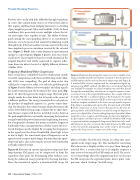
Figure 4A illustrates in current signal-processing terms how long-duration FM signals can be compressed to form the equivalent short pulse for determining delay without sacri- ficing the enhanced energy provided by the long duration. Here, the transmitted signal is a downward FM sweep (90
Figure 4. Diagrams illustrating three types of receivers capable of uti- lizing essentially all of the information contained in the waveforms of a FM broadcast and an echo to determine target range and shape. A: A matched-filter receiver implemented by contemporary digital sig- nal-processing (DSP) methods. The FM echo is received and digitized into multiple-bit samples at a fixed sampling rate and then passed through the matched filter, which has as its impulse response a time- reversed version of the original FM broadcast. For a single reflection (a simple FM echo is a delayed replica of the broadcast), the output is the cross-correlation function (XCR) of the received echo with the broadcast template embodied in the time-reversed impulse response. Echo delay is unambiguously registered by the main peak of the XCR. B: Pulse compression, or chirp, receiver that operates on the time-fre- quency pattern of the FM broadcast instead of using the impulse re- sponse of a digital filter. Countervailing frequency-dependent delays inside the receiver compress the FM sweeps of echoes into XCR pulses. C: Spectrogram correlation process in which the broadcast FM sweep is registered and then propagated along neural delay lines to be avail- able whenever an echo is received. The match between the FM sweep in the echo and the propagating trace of the sweep in the broadcast replaces the chirp receiver’s compression of the sweep.
kHz to 10 kHz). The FM echo returns at a delay that corre- sponds to the target range (dt). This method for converting FM echoes into a display of delay is to pass them through a matched filter, a receiver that has as its impulse response a time-reversed version of the FM broadcast itself. The receiv- er uses knowledge about the original broadcast to telescope the FM sweep into the equivalent pulse, hence, pulse “com- pression,” which “dechirps” the FM sweep.
46 | Acoustics Today | Winter 2017
