
Page 35 - Fall_DTF
P. 35
A ,_ B c
*3 ¥~?"‘“ white Hem Ian ‘J Radiated Acoustic Pressure
,4 ‘;_~e‘.‘ frequencies)
,r,T_\ , 3‘, «----M.
‘:9:~:«:. J -M .
u... ' r ighl separaied
.,_,_, . ‘ /K inlo each color at
"" M ,v _ ditlerenz angles
i--- ’ 7 _ Input
53; _: —v Pressure = Pi, r _
_,. _ 4 . i --‘I '
"‘ L
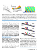
Figure 2. Examples l1J_;lSpfltl'l1l—fD—Sp€L‘fYl1l muppi;g. A: schematic showing unwrtgpped sl'mpll'fieil11mm1el;_’f the cochlea and basilar membrane
(zweiget al., 1974). e eaehlea is an example a a sputial—to—speetral eaupling eviee because iscrete equencies excite laeatians alang the
basilar memlrrane. B: a prism similarly perfarmsfrequencyspatial mapping by dividing a lrraadband signal, white light, inta its frequency
content as a fimctinn afspaee. c.- acoustic Ieuky wuve antenna (LWA) aflength L. with n unit eells and input pressure P , radiating inta the
surrounding medium at angle 9 according to the frequency of the signal. The eaardinate system y and z defines the rudiution and waveguide
directions, respectively. The magnitude afthe radiated pressure deereases exponentially alang the length af the antenna as energy leaks out af
the waveguide. The LWA displays a spatiul—to—spectrul mapping because each frequency travels at a dxferent phase speed and thus radiates at
drjerent angles inta the surraunding medium.
one is able to tailor dispersion in a waveguide to create an ,
acoustic LWA, it is possible to create frequency-dependent E U no
directionality of the LWA. Stated another way, a LWA SI " rm
1
enables the mapping from different frequencies (spectral Nowtclletilng '
components) to a particular radiated acoustic field (that is, Bwndaw mmdum
a spatial acoustic pressure distribution). This spectrum-to-
spatial mapping is important in other areas of acoustics as 5
well, including our ability to hear. The place theory of pitch ' Periodic
of the basilar membrane in the inner ear partially explains Holes
how the cochlea processes different frequencies (Zweig et
a.l., 1974). In a simplistic model of the cochlea, the geometry
and material properties of the basilar membrane (Figure
2A) result in each frequency exciting a different region of the \ _
membrane. Similar spatial-to-spectra.l mapping describes I Me‘a'"a‘e"a'
the physics behind an optical prism, as seen in Figure 213, "W5
splitting the frequency components into different directions. Membranes
From Electromagnetic to Acoustic
Leaky Wave Antennae _ _ _ _ _
Electromagnetic LWAs have existed since the 1940s (Hansen, Esme 3' Cmfiisemwml WW5 of mm? ‘mm W85 ofucolfim LW/B"
Th d_ _ d _ _ f I k d _ All of the LWA geometries have 11 single transducer (right) and 11
194°)‘ 9 “°‘“°“ 3“ ‘“‘"‘5“Y ° 9“ 9 “°°“5“° °’ nanrefieeting boundary (left) as well as a unifann tress seetian. In
electromagnetic Energy’ can be Contmlled in 3 Similfl all cases, the vertical dashed line aarrespands ta lrraadside (ml). The
manner to that of a far more complicated array of phased unifm-rn—sli't structure (rap) is the most straightforward reulizatinn,
sources. Therefore, what would conventionally require tens With 07 '4’”f7"’" 5”‘ 5”’ i" the Side "fth9 W“"eZ"id9- P5’i”'1i‘P9’f0’“’
or hundreds of mm (Len Powered) sounm each with tlons(hoI;s;1nIddlz)ci1n lrelnclujedlnsteadof-a unrfarmslrtta allaw
electronics for precise phase control, can be achieved with fa’ mm .3513" tunabllxly By ad mgapemdm filmy Ufmemlnanes
_ _ I d :1 _ _ d (bottom) interspersed with the holes, a metumuterlul Structure 15 reul—
3 “"819 5"“? 9 5°“““ ““ 3 P“’ Y P“5“’° (‘te-v ““P°‘”"° * ized that allows far full forward (+900 to lmekwuri1(—90°) steering.
with no additional electronics) MA. The simplest exnnpie Pm-ple,grun, andrzdurrmvs, difierentsteeringungles corresponding
of this is achieved by cutting a uniform, continuous slit in to low, middle, and high frequencies, respectively.
the side of a waveguide, as seen in Figure 3, top.
Fall 2013 | Acoustic: Today | :13
