
Page 61 - Fall_DTF
P. 61
I I l I r
Y. I .....,., _ ‘
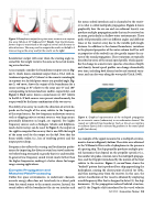
1 1 j ‘ i r V the ocean-seabed interface) and is channeled to the receiv-
{ ' l. -V ‘ u‘ _v, ‘I er in what is called multipath propagation. Figure 4 shows
‘ J I _‘ illl I [ graphically how the air-sea and sea-sediment layer(s) can
ll 1 V - ' I i _ ~ ‘ l_ » _ ; produce multiple propagation paths that can be received on
‘ ’ " an array, particularly in shallow water environments. These
Figure 3. Beamformeroutputfor a plane wave lncxaenr an a unxjurm Paths will Poieriiiaiiy arrive at different angles and different
line array (UL/_§) at 3f)“ (red) and 160° (black)._Nate that the beani— times at rile receiver army due re the Variable Parh length
farmer nutput is maximized at the angle nfarrlval and decreases in _ . _ . . .
. . . distance. In addition to the channel boundaries, variations
ether directions. The array aseal to compute the results on the left rs 5 _ _ _ _
times as lung as the array asealfar the results arr the right. In the PhY5lCe1 Properties of the water column Itself (as W211
as properties of the seabed) can also greatly impact the na-
beamformer output will occur when the steering angle as- mm °_fthe_s°“nd Propagation‘ These Variations fife typically
sumed for me weigh vector is the same as the actual inCom_ described in terms of the sound speed profile, which quanti-
. . . fies the change in acoustic mve speed as a function of depth
ing wave direction. _ _
and density. Sound speed profiles can change dramatically
A5 3“ "-x3mPler Clmsidef the beemfmmef °“'3P“‘3 See“ in Fig‘ over time, including both diurnal cycles and seasonal varia-
ure 3, which shows simulated output from a ULA with in- tions, and can 3150 very along the mve Pat},(UriCk1 19g3)_
terelement spacing of M2 (where A is the acoustic wavelength)
in response to a far-field point source at a specified angle. Fig-
ure 3, red curve, shows the output of the beaniformer for a WNW “M-V
source arriving at 30“ relative to the array axis (0" and 180" 4
corresponding to forward a.nd rear endfire, respectively). a.nd I _ -' I
Figure 3, black curve, shows a sound source at 160“ relative V V, l e
to the HLA. I.fboth sources were present simultaneously, the ‘ . . é
output would be the linear combination of the two curves. ‘
The ability of an array to resolve the direction of arrival de- l
pends on the length of the array relative to the frequency
of the sound source. For low-frequency underwater sources,
such as shipping noise or seismic sources, very large arrays, Figure 4. Graphical representation of the multipath propagatinn
Pmemiauy kflomeiers in lengih, are required‘ For higher for an acaustic source (submurinelin an underwater channel. The
frequency sources such as bioiogics (whales and dolphins), saahals are reflected frarrr boum1arles(such_a.s the air-sea rhterfaee
. er sediment layers) aha rs refracted by gradients in the sauna speed
much shorter arrays can be used. I.n Figure 3, the output on Pmfiie (W! Show")
the right is computed for an array that is one-fifth the length '
of the array used for the output on the lefi. Note that the
beam Widths Widen (i-e-r 1055 Of resolving Power) and ‘he An example of the signal measured in a multipath environ-
°“‘P“t POW" d’°P5- ment is shown in Figure 2, bottom. These data were obtained
Frequency also affects the sensing and localization perfor- in the Whlamlhte Rivehwith 3 hydmphohe in lhehresehce
mance by impacting the distance sound can travel underwa- of 3 Pashhg hhp‘ The sh’? Propeller Produces 'h“h‘_Ple sP_eC'
ter before being attenuated so greatly that it is undetectable. "31 hanhomcs ‘hm depehhl oh the Pmpeheh speclfics (“e"
I.n general, low-frequency sound travels much further than the ““'“b" °f5P°ke5r .1018?-I011 rate), the multipath propaga-
the higher frequencies, making it a better choice for longer h°h‘_md the D 0P P1?‘ mlrhduced by the "who" ofthe boat
rmge_sensing applications‘ relative to the receiver. Figure 2, curved lines, shows the
“bathtub” pattern that is produced by a ship approaching the
Domplax Propagation and hydrophone, nearing the closest point of arrival (or CPA).
Nlabohad Field Processing and then moving away from the receiver. In this case, the
Unlike free space environments, in underwater channels, correct classification of the vessel is obtained by employing
acoustic energy often does not travel only via a direct path a multifrequency filter that is designed to detect (1) the ship
from the sound source to the acoustic receiver. I_nstead, the harmonics, (2) the propagation-induced bathtub structure,
sound reflects off the boundaries (the air-sea interface and and (3) the Doppler shift introduced by the vessel velocity
Fall2018 | Acoustic: Tnduy | as
