
Page 49 - Winter 2020
P. 49
Auralization
Motivated by “visualization” as used for visual rendering, Kleiner et al. (1993) coined the term “auralization” in the context of room-acoustic modeling. They did this when they reviewed research activities in the field of room-acoustic simulations in the early 1990s, including computer-aided modeling in the form of both numerical simulation and experimental measurements in physical models. Summers (2008) notes “that auralization represents acoustic modeling as the agent that performs the rendering for the purpose of auditory perception and the sound events being rendered are created via simulation.”
In an overview of reverberation techniques, Välimäki et al. (2012) convey the idea that the focus of room-acoustic modeling is to obtain room responses by computational simulation, whereas Xiang and Blauert (1993) developed binaural auralization using binaural measurements in physical scale models. Those scale-modeled responses are processed, leading to binaural samples that can then be rendered for auditory perception. Vorländer (2008) also uses the term auralization to encompass any process that yields sound samples through modeling, synthesis, or experimental measurements. Therefore, auralization collectively encompasses both the modeling process and their results (Summers, 2008). In recent years, auralization has become an effective design tool to support acoustic designers in their innovative designs (Hochgraf, 2019). In this paper, we make a further distinction between simulation-based and measurement- based auralization and concentrate on the simulation part.
Linear time-invariant systems are often used to describe sound transmission from sound sources to receivers in room-acoustic enclosures. The transmission from one sound source to one monophonic receiver within a space is fully described by the one-room impulse response (RIR). A linear convolution of the RIR with sound signals recorded in an anechoic environment, being free from any reflections, yields sound samples as if the sound travels from the sound source in the space and arrives at the monophonic microphone.
For a binaural-listening situation, binaural RIRs characterize sound traveling through the room when they arrive at the listener’s two ears (Xiang and Blauert, 1993). The linear convolution of the binaural RIRs with reflection-free sound samples leads to one pair of
binaural sound samples. This convolution is typically implemented in the frequency domain using fast Fourier transform. When these sound signals are displayed properly to the two ears of the listener, the listener will perceive auditory scenes as if the individual were sitting inside the enclosure. The binaural auralization via room-acoustic modeling and the virtual auditory reality are evolved from this fundamental principle (Vorländer, 2020).
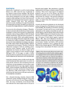
Crucial to the binaural auralization are the directional and spectral properties of the binaural receiver involved in the modeling. The external ears of a listener, consisting of two pinnae, the head, and the torso, encode spatial information of the incident sound field into only two channel signals in specific filtering. Head-related transfer functions (HRTFs) represent the transfer functions of the filtering in the frequency domain. In the time domain, they are known as head-related impulse responses (Blauert, 1997). They can be obtained in the form of a databank established in the early days through extensive measurements (Gardner and Martin, 1995) and later by numerical simulations such as applying the finite- difference time-domain approach. With advanced optical scanning of three-dimensional (3D) objects such as the
Figure 2. Three-dimensionally (3D) printed models using the meshing data of an artificial head for validation against the original grid mesh around a popular artificial head with pinnae. The original mesh was created for finite-difference time-domain simulations of head-related impulse responses. Distance errors between the original mesh and the 3D printed head replica (referred to as the Hausdorff error) are largely less than 1 mm, indicated by a pseudocolor scale, which is of sufficient accuracy to represent the pinnae and the head. Reproduced from Prepelita, et al., 2020, with permission.
Winter 2020 • Acoustics Today 49
