
Page 10 - Winter 2008
P. 10
quality of the TR reconstruction.
As waves simultaneously arrive at the focal location, they
interfere. The spatial distribution of the focus is limited by 12
the diffraction limit (see Fig. 7). The diffraction limit is reached when a sufficient number of waves constructively interfere at the focal location. An important consideration regarding the spatial distribution of the TR process is that not all the energy that is broadcast arrives at the focal position at the focal time. Notice the omnidirectional radiation pattern illustrated in Fig. 6. Some of the energy radiated in the rebroadcast step goes elsewhere into the medium. This ener- gy does not retrace the paths traversed in the forward propa- gation, and equates to noise, diminishing focal quality (note the energy present at other locations in space at the time of focus in Fig. 2 and Fig. 4). Finite sized transducers compound this effect.
In the experimental application of TR, transducers must be used in a TRM to detect and rebroadcast energy. These transducers can “color” the energy they detect and transmit. For instance, frequently, piezoelectric transducers are used.
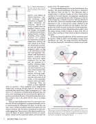
Fig. 6. Pictorial demonstration of two different implementations of Time Reversal (TR): (a) source emission, (b) standard TR and (c) reciprocal TR. Colors corre- spond to those found in Fig. 5. The solid lines correspond to the first emission of energy (red colored pulse in Fig 5c), while the dashed lines correspond to the sec- ond emission of energy (blue colored pulse in Fig 5c).
Fig. 5. Temporal representation of the steps used in Time Reversal. Colors correspond to those found in Fig. 6.
iprocity is not broken by velocity dispersion,11 mul- tiple scattering,12 mode conversion (as happens in solids),11 anisotropy, nor refraction. Spatial reci- procity is broken when the medium’s velocity struc- ture changes. An example is a medium where fluid is flowing thereby creating a disruption of the velocity structure, or a medium that experiences changes in temperature, altering the wave velocity in the medi- um. Attenuation in a medi- um does not break spatial reciprocity either, as long as the attenuation is linear with wave amplitude (con- sidered weak attenuation); however, nonlinear elastic effects may break spatial reciprocity. This can hap- pen, for instance, in a medium exhibiting ampli- tude-dependent attenua- tion that is hysteretic in its stress-strain response. This behavior is seen for instance, with large ampli- tude waves in rocks or materials with cracks. In all media, as wave amplitudes increase, waves may exhib- it distortion. These are known as finite amplitude
13
waves in acoustics. Finite amplitude waves progressively
steepen with increasing distance from the source and may
14
reversible.
There are some applications where it is necessary to con-
duct the TR back propagation in a numerical model, such as in reconstructing an earthquake (see later). To do this, one must create a numerical velocity model that mimics the real velocity structure that the waves encountered in their for- ward propagation. The accuracy of the velocity model is cru- cial to the degree of spatial reciprocity between the experi- mental system and the numerical model, and therefore the
and found that, provided shock formation does not occur, wave steepening can be reversed and thus spatial reci- procity is not broken; however, if shock formation does occur then energy is lost to the shock and the wave is no longer
eventually form shock waves. Both Cunningham et al.
Tanter et al.
15
8 Acoustics Today, January 2008
