
Page 41 - Winter 2011
P. 41
the support structure is the more com- monly encountered condition.
The design of floors for recording studios and critical listening rooms presents an interesting acoustical chal- lenge, which utilizes these principles. Ultimately the goal is to obtain an environment where recording, listen- ing, and sound mixing can take place without outside influences. Often the building sites, which are the most attractive to owners, due to price, loca- tion, or availability, are those which suffer from negative external influ- ences of noise and vibration. This arti- cle discusses three studio projects, each of which was strongly influenced by external factors, and how technical solutions had to be developed that addressed them.
Studio 1—Railroad noise
A well known post-production
company with property in Burbank,
California, wanted to construct side-by-
side screening rooms to be used for high end video post- production work. The rooms needed to be isolated acousti- cally from each other so that they could be used simultane- ously, without audible sound transmission between them. Since the building was already owned by the client it was the logical location for the facility. The two major acousti- cal challenges were the studio adjacencies, and a main line railroad track 75 feet away, where trains passed by about once every twenty minutes. A major freeway lay on the other side of the rail line but it was at a lower elevation and the peak truck noise level was much less than that of the locomotive engines and horns.
The first step was to measure the sound and vibration of the trains. A typical engine created a maximum noise level of 87 dBA at the exterior of the building. The loudest engine octave level was 100 dB at 63 Hz. The train horns were some- what higher overall at 95 dBA, with the highest octave band being 92 dB at 500 Hz. Surprisingly, the floor vibration in the existing slab was not noticeable inside the building.
The existing building was a concrete block (concrete masonry unit or cmu) structure with a lightweight plywood roof. The building had existing office space and was used for shipping and receiving. The shipping was important since there were lightweight rollup doors to accommodate pallet loading.
The studios were designed as a separate building within the existing space. We planned on floating floors built into a depressed slab so that handicapped access would be accom- modated without ramps. The first step was to model the sound transmission between theaters. We were aiming for a Sound Transmission Class (STC) rating of about 80 with sig- nificant low frequency isolation.
The normal approach to the design of adjacent studios is
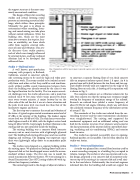
Fig. 2. Separation walls for music spaces to provide a given noise reduction between adjacent rooms (Klepper et al. 1980).
to construct a separate floating floor of 4 in thick concrete slab on neoprene isolators spaced about 2 ft apart. An 8 in grouted cmu wall is built between the two floors and two sep- arate double drywall walls are supported on the edge of the floating floor on each side. A drawing of the separation wall is shown in Fig. 2.
The neoprene isolators act as vibration isolators for the slab. One concern was that the spring mass resonance might overlap the frequency of maximum energy of the railroad. Research on railroad lines yielded a center frequency of about 30 Hz for rail engine vibration, which was well above the calculated resonant frequency of the slab/isolator system of around 7 Hz.
The remainder of the studio was isolated from the sur- rounding structure and the noise transmission calculations were straightforward. The existing roof supported the mechanical equipment and an additional ceiling roof was built for the interior structure. Duct silencers were located at the duct penetration of the interior shell to control both heat- ing, ventilating and air conditioning (HVAC) and exterior break-in noise.
The studio has operated successfully since its opening. Railroad passbys are not audible. The first film edited in the studio was Avatar.
Studio 2 – Structural limitations
A studio was planned for a second floor location used by a music recording company in a building they occupied in Atlanta, Georgia. The architect, who was experienced in stu- dio design, proposed a 4 in concrete slab on neoprene isola- tors on top of the existing 4 in concrete slab and a wall simi- lar to that used above. Unfortunately the structural engineer informed him that the building slab would not support the
Professional Studios 37
