
Page 42 - Winter 2011
P. 42
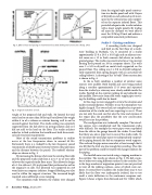
 Fig. 3. Effect of mass and spacing on transmission loss; Ideal double panel construction (Sharp, 1973)
  from the original triple panel construc- tion to a double panel wall with 3 layers of drywall on each side and an 18 in air- space in the critical areas, each support- ed on the separate isolated floors. This provided adequate side to side isolation with a lower weight penalty. By trading off mass for distance we were able to meet the 30 lb/sq ft limit and achieve a comparable acoustical performance.
Studio 3 – Existing conditions
A recording studio was designed and built on the first floor of a multi- story building in Burbank, CA. It consisted of a studio approximately 25 ft x 20 ft x 10 ft high and an adjacent con- trol room on a 12 in thick concrete slab above an under- ground garage. The studio was constructed on a 3 in concrete floating floor poured on 3/8 in neoprene sheets. The walls were 2 x 5/8 in drywall on metal studs supported on the poured floor. The ceiling was 2 x 5/8 in drywall independ- ently supported from spring hangers with an acoustical tile ceiling below it. A drawing of the “as built” floor construction
is shown in Fig. 4.
In the as built condition a number of exterior noise
sources were audible. Both footfall and carts being pushed along a corridor approximately 15 ft away and separated from the studio by a stairway were clearly audible inside the studio. Footfall on the exterior parking lot and sidewalk was also audible. Flow noise from cold water supply pipes servic- ing the building could also be heard.
At this stage we were engaged to review the situation and make recommendations. Needless to say the atmosphere was highly charged. The owner had just completed an expensive renovation of the studio and was expecting to use it. There was not only the sunk cost but also the time and expense of the repair plus the possibility that the new construction would not cure the problem.
The configuration was technically complex. The intrud- ing sources were complicated and the transmission paths were difficult. For example the water pipes were suspended from the slab in the garage beneath the studio. It was likely that there was also a pipe riser in one of the studio walls. To try to isolate the water pipe noise we independently suspend- ed the piping beneath the slab on temporary wood supports. This reduced the pipe noise somewhat, at least enough that it was felt that the level was low enough for recording. Thus this part of the problem could be treated with hanger isolators for the piping.
The footfall noise was tested using a tapping machine in the corridor. The results are shown in Fig. 5. We did a num- ber of other tests using different surfaces in the corridor. Due to the large number of origination points it was not practical to treat all the walking surfaces, some of which were out- doors. It seemed best to address the studio floor since it was likely that the floor was inadequately isolated, due to too small a static deflection in the continuous neoprene mat. Figure 6 shows a figure from Beranek and Ver (1992) which
 Fig. 4. Original studio floor as built.
 weight of the proposed slab and walls. He limited the total static load to no more than 30 lbs/sq ft but allowed the weight within 6 in of a column or exterior bearing wall to not be counted against that limit. The studio ceiling was separately supported from the slab above on spring isolators and so it did not add to the load on the floor. The studio architect asked us to find a solution that would meet both his acousti- cal and structural requirements.
Most of the sound transmission problems in studios occur at the low frequencies down to around 40 Hz. Fortunately there is a tradeoff in the low frequency sound transmission of double panel systems between the panel mass and the distance between the panels. The tradeoff relation- ships are shown in Fig. 3.
By increasing the distance between the existing floor slab and the proposed studio slab from 2 in to 7 in we were able to lower the required studio floor mass. This allowed a design of a 1.5 in slab on 1.125 in plywood that performed as well as the original 4 in slab. The plywood was supported on 2x6 wood joists on neoprene isolators. Stepped blocking was also used to stiffen the support structure. The increased height required some additional access ramping.
The separation walls between the studios were changed
38 Acoustics Today, January 2011
