
Page 43 - Winter 2011
P. 43
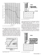
  Fig. 5. Studio noise from hallway tapping machine.
  Fig. 7. First step of the repair process.
 than up through the floor. If we could support the walls we could replace the floor. After much thought, I realized that the drywall would support the walls.
I devised a construction plan, illustrated in the following sketches. Figure 7 shows the first step, which was to remove lower six inches of drywall from the existing walls and to jack hammer out the center portion of the concrete floor down to the garage slab, leaving the outer 6 in ribbon of floor slab on the neoprene sheet to support the studio wall studs.
In the next step, shown in Fig. 8, a section of the remain- ing outer floor approximately 2 feet wide was chipped out from under a portion of the wall support structure. The dry-
 gives a negative attenuation for footfall noise at low frequen- cies resulting from a continuous underlayerment.
The problem was then to try to ascertain how to build an isolated floor given the existing condition. We knew that a floating floor on proper isolators would solve the problem. The difficulty was that we did not have sufficient height and since the existing studio wall structure was supported on the floating slab, we would have to devise a way of supporting the studio while we replaced the floor. Fortunately the electrical and audio wiring came down the walls from above rather
  Fig. 6. Improvement in impact noise isolation, ΔLn , for a resonantly reacting float-
ing floor (after Beranek, 1992). Fig. 8. Second step of the repair process.
Professional Studios 39
