
Page 44 - Winter 2011
P. 44
The new structure was poured to exactly match the elevation of the previous slab. Once the wall drywall and flooring were replaced, the piping noise, footfall, and cart movement in the corridor were no longer audible in the finished studio.
Summary
Vibration isolation is a critical part of building construc- tion particularly in studio floors. To work properly there must be adequate deflection in the support system to yield a resonant frequency well below the frequency of the intrusive noise and vibration. When there is too little deflection in the support system, poor isolation will result. Too much deflec- tion and the system can become unstable. In wall and floor construction there is a tradeoff between the mass of the com- ponents and the spacing which can be utilized to advantage. The lesson is that although we would like to design projects in the same familiar way every time, it is not always possible to do it. Given the obstacles we encounter, we have to use the principles we learned to craft new creative solutions.AT
References
Klepper, David L., Cavanaugh, William J., and Marshall, L. Gerald (1980). “Noise control in music teaching facilities,” Noise Control Eng. J. 15(2), Sept/Oct 1980.
Long, Marshall (2006). Architectural Acoustics (Elsevier, Oxford). Ruzicka, Jerome E. (1971). “Fundamental concepts of vibration
control,” Sound and Vibration magazine, July 1971.
Sharp, Ben H. (1973). A Study of Techniques to Increase the Sound Insulation of Building Elements, WR 73-5 (Wyle Laboratories, El Segundo, CA, June, 1973).
Beranek, Leo L., and Vér, István L. (1992). Noise and Vibration Control Engineering Principles and Applications, Ch. 9, “Interaction of Sound Waves with Solid Structures” (John Wiley & Sons, New York, 1992). This material is used by permission of John Wiley & Sons, Inc.
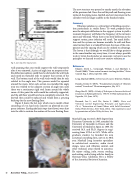
Fig. 9. Last step of the repair process.
wall spanning that area would support the wall temporarily after it was removed. A piece of angle iron on neoprene dou- ble deflection isolators could then be slid under the wall track and raised on threaded rods to support that section of the wall. The bottom track of the wall studs would then be tack welded to the angle iron. This process would be repeated around the room. After each section was installed the angle iron was welded to the adjacent section of angle iron until there was a continuous rigid steel frame around the whole room. At this point the walls would be resiliently supported, and the old floor would have been completely removed. The drywall then could be replaced and would form a pouring backstop for the new floating floor.
Figure 9 shows the last step, which was to install a floor consisting of 2 in hard rock concrete on plywood on neo- prene isolators. Earthquake limit stops (not shown) were shot into the slab to restrain the motion of the new floating floor.
Marshall Long received a BSE degree from Princeton University in 1965, attended the University of Grenoble in France and the University of Madrid in Spain in 1966. He received M.S. and Ph.D. degrees in engi- neering from UCLA in 1971. While still a graduate student, he founded his own acoustical consulting firm, now in its 38th year. Marshall Long Acoustics specializes in architectural acoustics, audio visual design, noise and vibration control, and other technical areas related to acoustics. He enjoys sailing, judo, soccer, reading, and writing, and is living with his family in Sherman Oaks, California. He is a Fellow of the Acoustical Society of America.
40 Acoustics Today, January 2011
