
Page 13 - Volume 9, Issue 3
P. 13
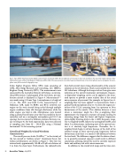
                                  Fig. 6. Top: 2008 F-35AA Joint Strike Fighter measurements at Edwards AFB. The microphones were located on thin rods attached to the top of the tripods. Bottom: Near- field measurements of the F-22A Raptor at Holloman AFB in 2009. The measurements consisted of a ground-based linear array of microphones and a rectangular 90-micro- phone near-field acoustical holography array.
Strike Fighter Program Office (JPO) team consisting of AFRL, Blue Ridge Research and Consulting, LLC (BRRC), Brigham Young University (BYU). The measurements were sponsored by the Australian Ministry of Defence, an interna- tional JPO partner. A photograph of the tied-down, pre-pro- duction aircraft is displayed in Figure 6. Measurements29,36 were made using 6.35 mm Type 1 microphones at a height of 1.5 m. The 2009 near-field F-22A measurements37 at Holloman AFB, made by BRRC and BYU, involved one engine on the static aircraft being cycled through multiple engine conditions from idle through afterburner while the other engine was held at idle. Microphones were located along a ground-based linear array that was parallel to the jet centerline and on a rectangular microphone grid (15.2 cm spacing) that was moved to different positions between run- ups (see Figure 6). For both experiments, data were collected at sampling rates from 96 – 204.8 kHz using a National
from both aircraft show strong directionality of the acoustic radiation in the aft direction, which is presumably due to the LSS turbulence. Although level maps such as these give some indication of the aircraft maintainer environment, frequen- cy-dependent weighting curves can be applied to the meas- ured spectra to provide a more realistic idea of the actual noise exposure of personnel. For example, in Figure 8 an A- weighting filter has been applied38 to measurements from a ground-based microphone array 11.7 m from the engine cen- terline of the F-22A, spanning from 3 m upstream to 28 m downstream of the nozzle. (This sideline distance is near where a maintainer might be.) The A-weighting filter approximates the frequency response of human hearing by removing energy from the lowest and highest frequencies, while slightly boosting levels in the 1-5 kHz frequency range. The A-weighted OASPL follows the unweighted OASPL until about 5 m downstream, indicating most of the spectral con- tent is at relatively high frequencies. Thereafter, the A- weighted levels begin to deviate because of the shift of the radiated energy to lower spectral peak frequencies farther downstream until there is a nearly 10 dB difference between the two levels. The difference suggests that the choice of met- ric to quantify personnel exposure could result in different conclusions, pointing toward the need to correlate exposure limits and auditory risk with various measures.
In addition to the overall level maps and the time-aver-
Instruments® 24-bit recording system.
36
Overall and Weighted Level and Waveform Characteristics
The overall pressure levels (OASPLs)36,37 in the vicinity of the two aircraft at “military power” (maximum thrust, but without afterburners) are shown in Figure 7. Note first the intense levels, approximately 150 dB re 20 μPa at a distance of 5 m from the shear layer. Furthermore, the radiated levels
12 Acoustics Today, July 2013
