
Page 18 - 2016Winter
P. 18
Seismic Surveys
be significantly displaced from the axis of travel by cur- rents, so a network of acoustic transponders (“pingers”) are used to relay the actual geometry of the array to the ship’s navigational displays and data-recording systems. As with many other aspects of towed seismic survey technology, the complexity of the streamer technology exceeds the limits that this short treatment can cover, but the terabytes of data streaming down the cables to the computers onboard the ship are only possible due to computer technology advances achieved in the past two or three decades.
2-Dimensional Surveys
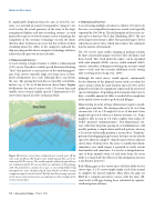
A vessel towing a single streamer is called a 2-dimensional (2-D) survey. It produces widely spaced downward-looking “lines” that generate a coarse picture of the underlying geol- ogy. Such surveys typically range over large areas of hun- dreds of kilometers on a side, although this is not always the case. The spacing between lines is typically several kilo- meters (e.g., 4, 10, or 20 km between survey lines). Figure 10 illustrates the mix of coarser scale 2-D survey lines and smaller areas of more tightly spaced 3-dimensional (3-D) survey lines typical of active oil and gas fields.
Figure 10. Seismic survey lines conducted over several years off the west coast of Africa. The longer, more widely spaced lines are 2-di- mensional (2-D) surveys. The smaller patches of densely spaced lines are 3-dimensional (3-D) surveys that are indicative of the geology, with the potential to contain oil or gas, or of existing fields being managed over time. Numbered grid: lease blocks on which energy companies may be invited to bid. The bid and the ensuing revenues to the owner state are based in no small part on the strength of the seismic survey data.
3-Dimensional Surveys
A vessel towing multiple streamers is called a 3-D survey. In this case, several parallel streamers are towed, each typically separated by 100-500 m. The full footprint of the receive ar- ray can be as much as 6 by 12 km (Hambling, 2016). The cost of the larger towed array is offset (the operator hopes) by the reduction in survey time, which also reduces the sound put into the marine environment.
The 3-D receive array enables imaging of geology overlain by more acoustically opaque structures like salt domes and dense basalt. This “look under the edges” can be expanded with wide azimuth (WAZ) surveys, radial azimuth (RAZ) surveys, and other techniques involving one or more sound source vessels and two or more additional vessels towing only receiving arrays (Long et al., 2006).
Although the ideal survey would operate continuously for the duration of the planned survey track, in reality the source array is silent for some fraction (up to 20-30%) of the planned track lines for equipment repairs and for protected species mitigations. Depending on the amount of lost survey data, a variable amount of effort is needed after completion of the initial survey tracks to go back and fill gaps.
Maneuvering an array of large dimensions requires consid- erable space and time. The turning radius of a 10- to 12-km streamer for 2-D or 3-D might be 10 or 12 km and a turn might take up to 8 h, whereas a shorter streamer (i.e., 6 km) might be able to turn in 3 h with a tighter turn radius (P. Seidel, personal communication). Two-dimensional sur- veys, with their large line spacing of several kilometers, will usually perform a simple down-and-back pattern, whereas 3-D surveys will usually perform a racetrack or “Zamboni” pattern of overlapping loops because the lines are too closely spaced to allow for simple U-shaped turns between adjacent survey lines. During turns, the array is usually shut down; sometimes, one small airgun is operated to verify system functionality and sometimes, it is used as a mitigation mea- sure to keep animals aware of, and away from, the array while it is turned off (the efficacy of this mitigation measure is not known, however).
Back-filling gaps in the survey lines will also differ by the survey type. A 2-D survey might simply circle back around to complete the missed segment. More often, the gaps are filled by a complex postsurvey course, with the most effi- cient track to fill gaps having been calculated by sophisti- cated navigation software.
16 | Acoustics Today | Winter 2016
