
Page 38 - Fall_DTF
P. 38
Acoustic Leaky Vtlave Aneenna A ,,_a 3 , A W, , ,, W , W,
lmrrvu , ,4 - '
A 100 Unit Cells su B Antenna Lenqlhl im> ""'“" 7':/l '- >~ ‘- >-—
% E
M arses,” V0 zswrr L1‘ 4 .. ..
-,; M I .w.a.m....nn 1 i=9 L=.1
40 2’. _ -I1n>.:VFnr_utuJ , L-.1
‘.1 5? _5"'w‘.‘s:T::':‘:*J J C _
E so - 5*
a fag _
E E "' L 2 .2 L - .3
20 E \‘
3 in u
,0 0 Yuma M) In .'r-as
+ as v is 2 75 x Lw/uengtn
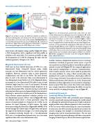
R (W ‘““"“’“ """‘°"“ Figure 5. A: twmiiimensianal, pnsitiveanly index LWA ean steer
Figure 5. A. similar to the ewe has 5.-aerate; in added. to ;;5j1}j:_f;;";;;;j;;f;t;:j§;;j§ mg.g;7;;,g;;;?;;;;;j:=,;;;:3
the main rudiutinglabe. seen clearly in the 100—unit ee11 army, where me‘ afmh mmdum is “W to my in azimuth M M as Show
the main zahe is net in the eenter afthe antenna (lzfi bluklinz) but . . . . 3
. . . _ m Nmfy et ul. (2015). c.- Vortex waves. In which the phase af the
IS mstead lnused {award the source end (red arrow). B: f€SUl1lfi0Vl of . . . . .
. . . wave is wrapped buck an rtsezfand whreh curries arlntul angular ma—
the antenna. defined here us the huifipawer hearnwrdth, rs improved . .
. . . rnentarn, can be generated by wrapping the LWA buck an rtsezfand
by ‘""‘“"”3 ‘he ""3”' ”f”"” LWA (N‘'’f’’ ”’ ‘'1'’ 2015“) steering through dgferent Vortex mndes by Varying the frequency af
excitatinn. Experimentally measured Vortex waVe—phuse pmfile using
min beam) and improve image quafity Figure 5A shows a_1.wA shows that a variety afvortex modes, L. are generated usinga
. . . _ _ Single antenna und varying the xnputfrequency (Nmfy et al., 2016b).
a LWA beampattern with a significant side lobe profile in R . . . . . . _
ed urmw, pmpagatxan dxreetwn msxde the waveguide. Hark ar-
addition to the main lobe. It is, however, possible to taper mwS_ W1,-“ted ,1,-mm-W,5_
the beampattern of a LWA by designing the taper into the
radiation geometry (simgusa at al“ 2012)‘ Another common configuration antenna array is to arrange
transducers circularly to generate vortex waves, a type of
EaY°nd “ha Linear A"‘5Y structured mve in which the phase is twisted like a corkscrew
Until now we have limited discussion of LWAs to a one- around 3 ceium_|nuii(1:igui—¢6(j) for arange0faPP1fiCa‘i0n§
dimenslonelw 11-“ear WeVe8“ide became many 5imPle from particle manipulation to acoustic communications.
e“te““e5 are °“e'di‘“e“5l°“el and ft“ Ieletlve geometric Until recently, acoustic vortex waves could be produced by
5t‘“P1lcltY Howeveew emennee mme in men?’ geometric two main methods: (1) using a fixed circular phase step,
configurations. and thus so can LWAs- The most obvious machined into a plate to introduce a fixed phase offset or
Place to Start is the eXte“5i°“ from 3 0“9'dimc“5i°n31 t0 (2) by using a electronic-heavy phased array of transducers
two-dimensional array (Naifv et al., 2015). Figure 6A shows (Hefner and Marston, 1999; Riaud et al., 2015). The practical
3“ ex“-mPle 0f 3 tW°'dtme“5i°m-I LWA “H9 t0 Steel" in b°th limitations of these approaches are overcome by wrapping a
e19V3tl0n (angle {mm the Z'3Xi5- 9) and azimuth Elevation linear acoustic LWA into a circle. This vortex wave antenna
steeflng is eehleved by 5WeePt“3 th"°“gh f‘e‘l“e“cYv 35 in uses a single transducer while having the ability to tune the
the one-dimensional LWA. Azimuth steering is achieved by vor[g_x modg by swegping thirough, as sgen in Figure 6Q
adjusting the relative pressure from multiple active elements,
resulting in constructive interference of the beampatterns. Looking Forward:
Finite-element analysis-predicted radiation patterns of a Leaking Vvhat Dumas Next
two-dimensional acoustic LWA is seen in Figure 613 where Looking forward, LWAs offer potentially game-changing
the leftmost panel shows a beam generated using two ways for acoustically sensing and imaging the world around
sources of equal strength at a frequency of 1.2 kHz. As we us. Although the potential savings in size, weight, and power
increase the input frequency of both sources, the single might provide a more efficient approach to the current state-
beam moves along the dotted line (Figure 6B, middle). If we of-the-art arrays while maintaining the sa.me functionality,
instead change the relative input strength from each panel, in some cases, the LWA can open up entirely new avenues for
the angle of the dotted line changes. It is worth noting that acoustic imaging. One example is a biomedical ultrasonic
the transducer-reducing benefits for a two-dimensional imaging array and its associated electronics. The size and
LWA over a two-dimensional phased array are even more power required to operate and image with these arrays make
significant than with a one-dimensional array. imaging in limited spaces, like in intravenous applications,
as 1 AI:uuI:l:I Tbday 1 H11 2013
