
Page 34 - Summer2020
P. 34
ARTILLERY LOCATION IN WWI
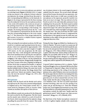
the positions of six or seven microphones were plotted on a plotting board (Figure 2; Mitchell, 2012). A catgut string was pinned at the midpoint between adjacent microphones; the strings stretched from this point to their corresponding time difference on the timescale. In Figure 2, the string is represented by the lines running from the midpoints between the microphone positions to the circles with numbers (the circles are not part of the plotting board but are only included to identify the microphones corresponding to that bearing). For example, the bearing determined from the No. 1 and No. 2 microphones is represented by the line that runs from the corresponding midpoint to the circle contain- ing “1-2.” The intersection of the strings indicated the gun location. In practice, a reliable location required three or more asymptotes.
When surveying the microphone positions, the SR team would try to maintain equal spacing between the micro- phones, which were separated by approximately 1,500 meters, so that the entire array had a length of roughly 7,500 meters. As the war progressed, the SR teams learned that they could distinguish individual guns when fired simultaneously by placing the microphones on the arc of a circle facing the enemy line, as depicted in Figure 2. The radius of the arc was the estimated dis- tance of the enemy batteries. Bragg initially thought this was “fussy” because of the extra complexity in laying out the line, but he later recognized the benefits. A captured German order forbade any battery to fire alone, think- ing that multiple batteries firing at the same time would confuse the Allied SR systems. But Bragg claimed that they could locate “almost any number of guns firing at once, the more the merrier” (Bragg et al., 1971), obvi- ously a hyperbole.
Microphones
Initially, both the French and the British used carbon microphones for SR. These were invented independently in England and in the United States around 1877. A recent article by Thompson (2019) in Acoustics Today contains an excellent description of these devices.
Three different sounds were produced by the firing artil- lery and recorded by the SR apparatus. The first sound was the muzzle wave, referred to as onde de bouche by the French, which was produced by the explosive charge propelling the projectile from the cannon. This sound
was of primary interest to the sound rangers because it radiated from the cannon. The second sound, although detected first because the projectile was supersonic, was the ballistic shock wave or shell wave recorded by the microphones as the supersonic projectile traveled over them on its way to its target. This was referred to by the French as onde de choc and is basically a minisonic boom radiating from the projectile. The third sound recorded by the microphones was the explosion of the shell as it impacted its target. The carbon microphones were sensi- tive to the shell wave, which was higher in frequency than the muzzle wave. This issue frustrated the BEF sound rangers in their early efforts because it complicated the interpretation of the signals because the shell wave was dependent on the caliber of the gun and varied with the range and direction of fire.
During this time, Bragg was billeted in a farmhouse at La Clytte in Flanders. The privy, located in an annex just off the kitchen, was sealed except for the hole beneath the seat:
“one sat on the only aperture between interior and the outer air” (Bragg et al., 1971). When a British 6-inch gun, located aquartermileaway,fired,“anyonesittingontheprivywas slightly, but perceptibly, lifted off the seat” (Bragg et al., 1971). This led Bragg and his colleagues to conclude that the gun sound produced a large amount of low-frequency energy that could be exploited for SR (Mitchell, 2012).
Corporal Tucker’s experiences led to a solution. Tucker had joined Bragg’s section on Kemmel Hill from the Phys- ics Department at Imperial College, where he had been performing experiments in the cooling of very fine hot platinum wires, called Wollaston wires (see bit.ly/3d5u5Jf).
The tarred-paper shack in which he was staying at the time, with Bragg and others, had holes or tears in it. When the guns fired, jets of cold air annoyed him as he lay on his bunk. Tucker had the idea of using these jets of air to cool Wollaston wires. The first successful experiment involved stretching a thin wire over the opening of an empty rum jar and blowing on it. Then they obtained
“proper wire” from England and stretched it across a hole they had drilled in a discarded ammunition box. The new microphone worked; the shell wave “hardly made the galvanometer quiver” while the gun wave “gave an enor- mous kick” (Bragg et al., 1971; Mitchell, 2012).
The final form of the Tucker microphone consisted of a 23-liter (5-gallon) tinplate cylinder with conical ends,
34 Acoustics Today • Summer 2020
