
Page 35 - Summer2020
P. 35
manufactured in England by the Cambridge Instrument Company. One end of the cylinder was closed. A short, open tube was inserted into the other end. The hot wire grid consisted of fine platinum wires stretched across a square opening (4.5-centimeter aperture) in a mica disk, which screwed into the end of the open tube (Tucker and Paris, 1921). The original devices worked poorly due to resonances, but the problem was mitigated by drilling four small holes in the side of the cylinder. Tucker micro- phones were provided to all British SR sections, whereas the French continued using systems with microphones.
The Tucker microphone is essentially a Helmholtz reso- nator; the low-frequency, long-wavelength muzzle wave caused the pressure of the volume of air in the cylinder to change uniformly as the acoustic wave passed over the microphone. This vibration caused the air in the tube or neck to move into and out of the container, cooling the platinum wires. Air moving in either direction cooled the wire, which had the effect of “rectifying” the signal by producing a current that was always positive (Bragg et al., 1971). Its resonance frequency was probably between 30 and 50 Hz, based on the cited dimensions. The four drilled holes would have dampened and broadened the resonance. Bragg reports that the characteristic frequencies of the guns were between 10 and 25 Hz, with larger guns at the lower frequencies. Tucker’s microphone was less sensitive to the higher frequency, smaller wavelength shell waves.
Harp Galvanometer
SR required that the signals produced by the micro- phones be recorded so that the time differences could be determined. These signals were recorded with different styles of galvanometers. In one arrangement, referred to as the télégraphe militaire (TM), electric signals from carbon microphones “would actuate marking pens on smoked paper” (MacLeod, 2000), probably in a way that is similar to a strip-chart recorder.
Lucien Bull designed and developed a recording device based on the string or Einthoven galvanometer, which had been invented in 1901 by Willem Einthoven. Bull’s version contained six wires, each connected to a different microphone. This was referred to as the “harp” galva- nometer. The wires were arranged in a plane parallel to one another and a half centimeter or so away from a plane containing 35-mm movie film. A light source pro- jected images of the wires onto the film, which advanced
at a constant speed. A magnetic field was applied in the direction perpendicular to the plane of the wires. Elec- trical current from a microphone, in the presence of the magnetic field, caused the corresponding wire to deflect, which was recorded on the film.
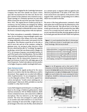
The motor of the harp galvanometer contained a wheel with spokes that would interrupt the illumination of the film at fixed intervals. This placed lines on the film at evenly spaced intervals, which permitted the time differ- ences to be accurately and more easily read. The type of record, reproduced from film, showing signals produced by German guns and detected with Tucker microphones,
Figure 3. A record reproduced from film of a German gun firing. S, shell wave arrivals; G, muzzle (gun) wave arrivals. From Trowbridge, 1920. See text for details.
Figure 4. An SR apparatus such as that used in WWI. Annotations in the border indicate that the plotting board was located at the bottom left. Just above this was the camera with the galvanometer to its right at the bottom center. The rheostats (right) were used to balance the circuits containing the Tucker microphones. Available at militarysurvey.org.uk. See text for
detailed explanation.
Summer 2020 • Acoustics Today 35
