
Page 36 - Summer2020
P. 36
ARTILLERY LOCATION IN WWI
is shown in Figure 3. In addition to time differences, the analyst could determine the caliber of the gun by noting the duration of the signal, which was an indication of its frequency; lower frequency signals produced by larger guns had a longer duration. The system designed by Bull, which had a faster response time than the stylus system used in the TM, was able to determine time differences to within 0.01 second (Bragg et al., 1971).
Bull made the first 50 galvanometers, whereas later ver- sions were manufactured by the Cambridge Instrument Company. A complete SR apparatus with galvanometer, camera, and plotting board is shown in Figure 4. Each Tucker microphone was connected to a wire of the harp galvanometer through a circuit containing a Wheat- stone bridge that contained rheostats used to modify resistances to balance the bridge; this particular system would have accommodated seven Tucker microphones.
The United States Enters the War
The United States officially entered the war on April 6, 1917. General John J. Pershing became the Commander in Chief of the American Expeditionary Force (AEF) in May 1917. HearrivedinFranceinJune,wherehewasintroducedtothe flash- and sound-ranging efforts of Britain and France. The newly formed US National Research Council recommended Augustus “Gus” Trowbridge, professor of physics at Princ- eton University, to organize the flash- and sound-ranging services. Trowbridge became a Major in the Signal Corps Reserve before being transferred to the Corps of Engineers in October 1917, where he served under Colonel R. G. Alex- ander, chief of the Topographical Section (Kelves, 1969).
Trowbridge met with the French in July where he was introduced to their SR systems. In the meantime, Colonel Alexander had been investigating the British and French
systems with the help of Lieutenant Charles B. Bazzoni, an American physicist who had volunteered while on a research fellowship in London. Bazzoni preferred the British system, referred to as the Bull-Tucker; although not as sensitive as some of the French devices, it was less delicate and not as difficult to use under demanding battle conditions. The AEF adopted the Bull-Tucker, and the British supplied the first systems (Kelves, 1969).
Theodore Lyman, a distinguished Harvard physicist, joined the team as a captain in the Signal Corps Reserve. He and Trowbridge sailed to Europe in September, eager
to start training and deploying flash- and sound-rang- ing sections knowing that the German Army would be concentrating its forces on the Western Front with the surrender of Russia in the east. They recruited officers from the Ambulance Service and troops from the Army Engineers who had already arrived in France. Lyman and Bazzoni set up a school for flash and SR at Ft. de St. Menge, near Langres, (see bit.ly/3d0vJvE) early in Janu- ary 1918 where they trained and fielded four flash and four SR sections by the end of the war.
Sound Ranging in Practice
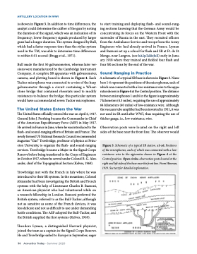
A schematic of a typical SR base is shown in Figure 5. Num- bers 1-6 represent the positions of the microphones, each of which was connected with a low-resistance wire to the appa- ratusshowninFigure4attheCentralposition.Thedistance between microphones 1 and 6 in the figure is approximately 7 kilometers (4.3 miles), requiring the use of approximately 64 kilometers (40 miles) of low-resistance wire. Although the vacuum tube amplifier had been invented in 1911, it was not used in SR until after WWI, thus requiring the use of thicker gauge, i.e., low-resistance, wire.
Observation posts were located on the right and left sides of the base near the front line. The observer would
Figure 5. Schematic of a typical SR station. x1-x6, Positions of the microphones, each of which was connected with a low- resistance wire to the apparatus shown in Figure 4 at the Central position. Open circles, observation posts located at the right and left sides of the base near the front line. From Hinman,
1919. See text for detailed explanation.
36 Acoustics Today • Summer 2020
